

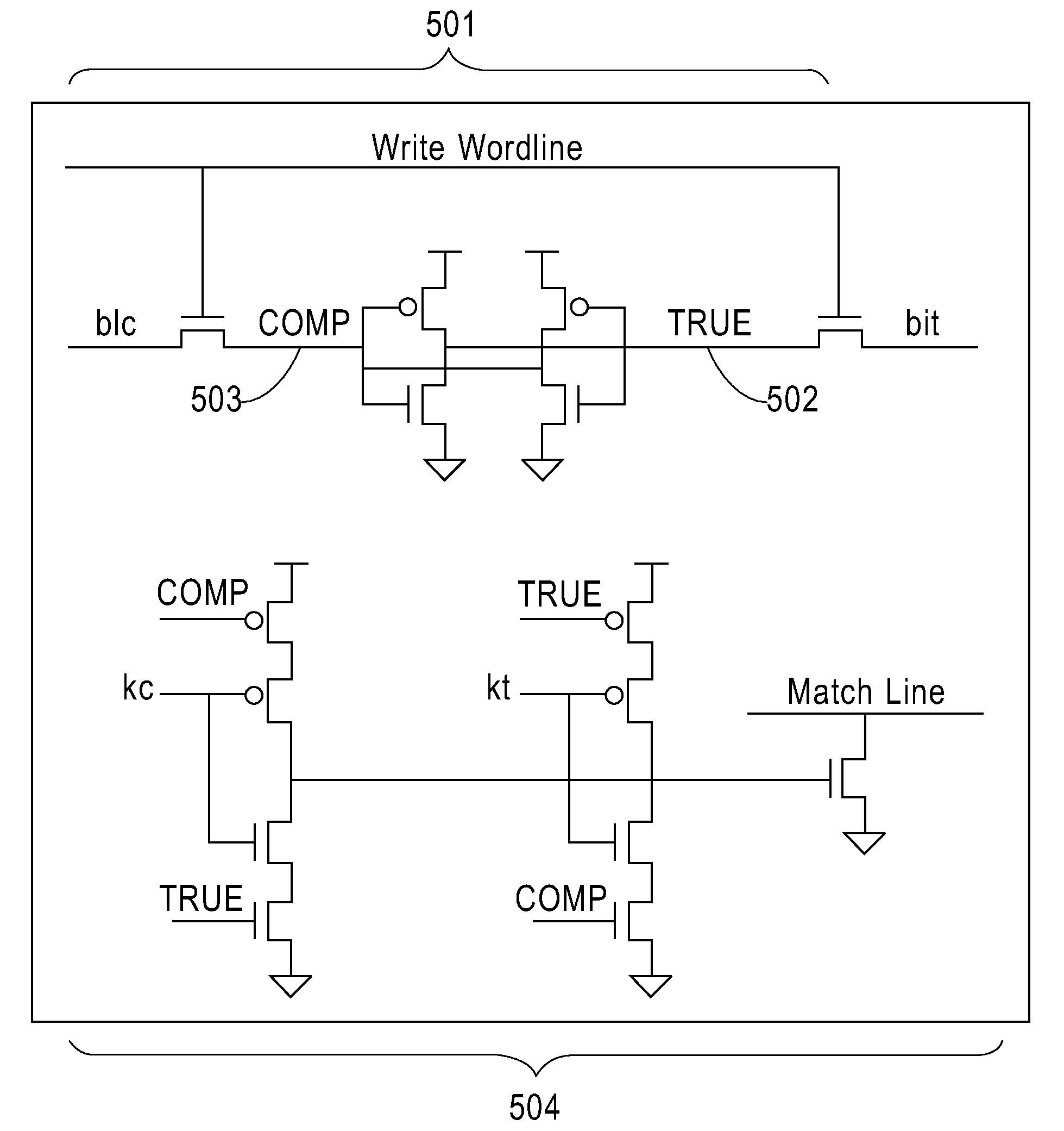
Multi-wafer 3D cam cell
a multi-wafer, cam cell technology, applied in the field of semiconductor structure, to achieve the effect of substantially reducing the negative effect of increasing the travel distan
- Summary
- Abstract
- Description
- Claims
- Application Information
AI Technical Summary
Benefits of technology
Problems solved by technology
Method used
Image

Examples
Embodiment Construction
[0037]The present invention, which provides a compact multi-wafer CAM cell and a method of fabricating the same, will now be described in greater detail by referring to the following discussion and drawings that accompany the present application. It is noted that the drawings are provided for illustrative purposes only. As such, the drawings included within the present application are not drawn to scale.
[0038]In the following description, numerous specific details are set forth, such as particular structures, components, materials, dimensions, processing steps and techniques, in order to provide a thorough understanding of the present invention. However, it will be appreciated by one of ordinary skill in the art that the invention may be practiced without these specific details. In other instances, well-known structures or processing steps have not been described in detail in order to avoid obscuring the invention.
[0039]It will be understood that when an element as a layer, region o...
PUM
 Abstract
Description
Claims
Application Information