Dual-band loop antenna

a loop antenna and loop technology, applied in the direction of resonant antennas, elongated active element feeds, radiating element structural forms, etc., can solve the problems of over-sized antennas, antennas that cannot cover only the bandwidth of the gms band, and cannot meet the requirements of cell phones being realized in thin-thickness, etc., to save manufacturing costs and simplify the structure

Active Publication Date: 2008-11-27
AUDEN TECHNO +1
View PDF2 Cites 25 Cited by
  • Summary
  • Abstract
  • Description
  • Claims
  • Application Information

AI Technical Summary

Benefits of technology

[0014]Further, the design of the dual-band loop antenna has a simple structure. The dual-band loop antenna can be directly formed on a dielectric substrate by means of printing or etching without any additional processing process to mount the antenna to a radio signal line or system ground plane, thereby saving much the manufacturing cost.

Problems solved by technology

When we have the aforesaid concealed cell phone antenna be used in a thin-thickness cell phone (of thickness about 10 mm or thinner), we will encounter a problem of over-sized antenna and will be unable to satisfy the requirements of having cell phones be realized in thin-thickness.
However, either a planar antenna or monopole antenna is used, subject to the limited space inside the cell phone, the antenna can cover only the bandwidth of the GMS band.
When the environment of use is changed, for example, when the user holds the cell phone with the hand or keeps the cell phone close to his (her) head, the large dielectric coefficient of hand or head will cause a frequency shift, resulting in a decrease in cell phone radiation efficiency.

Method used


Image

  • Dual-band loop antenna
  • Dual-band loop antenna
  • Dual-band loop antenna

Examples


Embodiment Construction

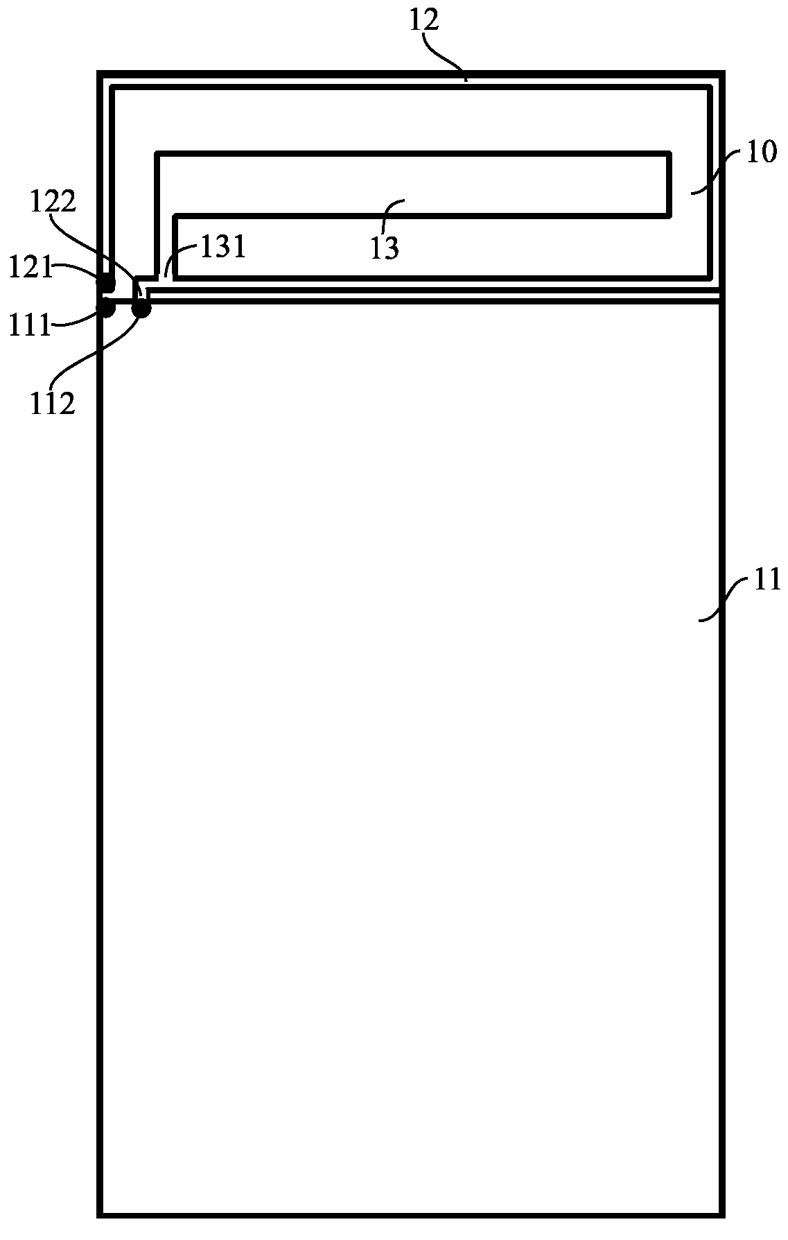
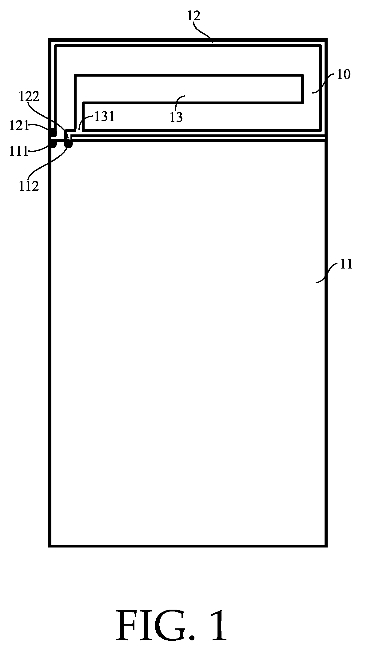
[0022]Referring to FIG. 1, a dual-band loop antenna in accordance with a first embodiment of the present invention is shown, which comprises a ground plane 11, a radiating metallic loop 12 and a radiating metallic plate 13. The ground plane 11, the radiating metallic loop 12 and the radiating metallic plate 13 are respectively formed on a dielectric substrate 10 by means of a printing or etching technique. The ground plane 11 shows a substantially rectangular shape, having a grounding point 111 and a shorting point 112. The radiating metallic loop 12 has a feeding end 121 and a shorting end 122. The feeding end 121 and the shorting end 122 are kept apart from each other at a distance not less than 5 mm. The shorting end 122 is electrically connected to the shorting point 112 of the ground plane 11. The radiating metallic plate 13 is surrounded by the radiating metallic loop 12. Further, the radiating metallic plate 13 has one end 131 electrically connected to a vicinity around the s...


PUM


Abstract

A dual-band loop antenna for using in a mobile phone for (890˜960 MHz)/DCS(1710˜1880 MHz) application is disclosed to include a ground plane in a substantially rectangular shape having a grounding point and a shorting point, a radiating metallic loop having a feeding end and a shorting end electrically connected to the shorting point of the ground plane and spaced from the feeding end at a predetermined distance, and a radiating metallic plate surrounded by the radiating metallic loop and having one end electrically connected to a vicinity around the shorting end of the radiating metallic loop and spaced from the shorting end of the radiating metallic loop at a distance less than 10 mm.

Description

CROSS-REFERENCE TO RELATED ART[0001]The present invention is a continuation-in-part of U.S. application Ser. No. 11 / 564,893, entitled DUAL-BAND LOOP ANTENNA, filed on Nov. 30, 2006.BACKGROUND OF THE INVENTION[0002]1. Field of the Invention[0003]The present invention relates to a loop antenna, and particularly, to a dual-band loop antenna to be built in a mobile telephone, which generates a half-wavelength mode and a full-wavelength mode of a radiating metallic loop thereof, and an additional half-wavelength mode by coupling between a radiating metallic plate thereof and the radiating metallic loop.[0004]2. Description of the Related Art[0005]Following fast development of wireless communication technology, a variety of wireless communication products have been developed and have appeared on the market. In wireless communication products, the antenna plays an important role. Under the tendency toward the design having light, thin, short and small characteristics, the height of the ant...

Claims


Application Information

Patent Timeline
Patent Type & Authority Applications(United States)
IPC IPC(8): H01Q11/12
CPCH01Q1/38H01Q5/371H01Q9/40H01Q7/00
Inventor CHI, YUN-WENWONG, KIN-LU
Owner AUDEN TECHNO
Why Eureka
Try Eureka