

Low-Loss Rectifier with Optically Coupled Gate Shunting
Patent Information
- Authority / Receiving Office
- US · United States
- Current Assignee / Owner
- HARRIS CORP
- Publication Date
- 2008-11-27
- Estimated Expiration
- Not applicable · inactive patent
Smart Images
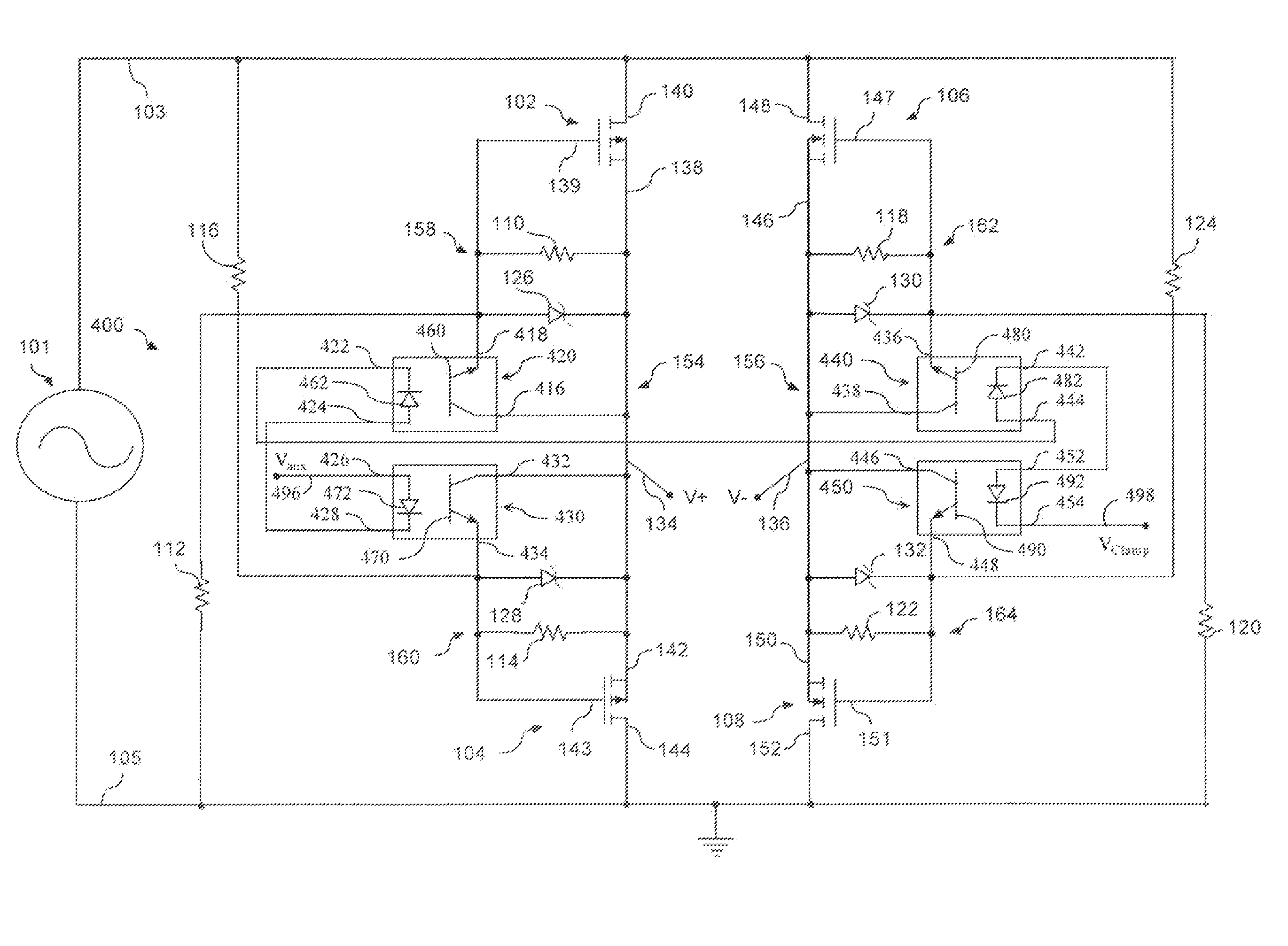
Figure 1 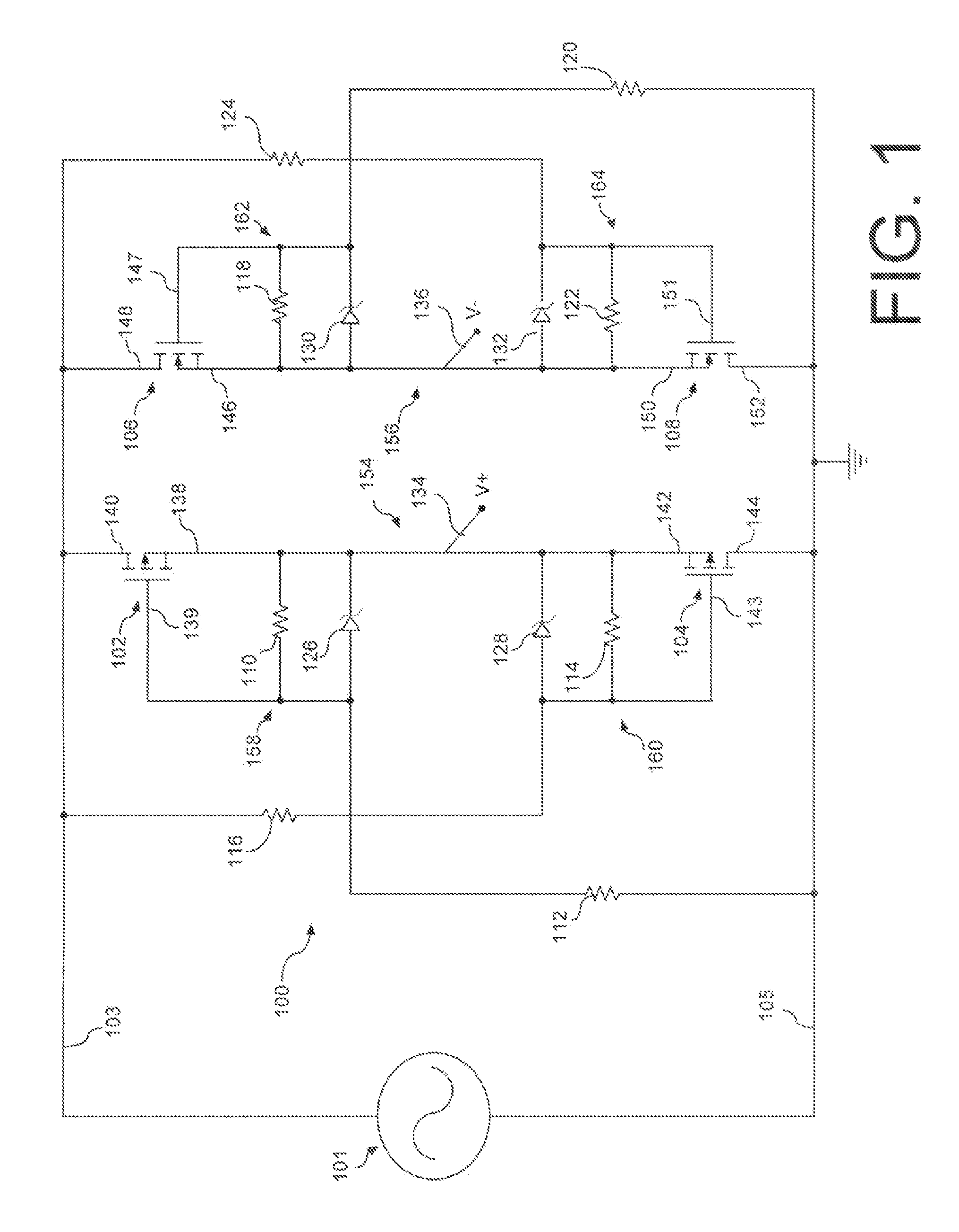
Figure 2 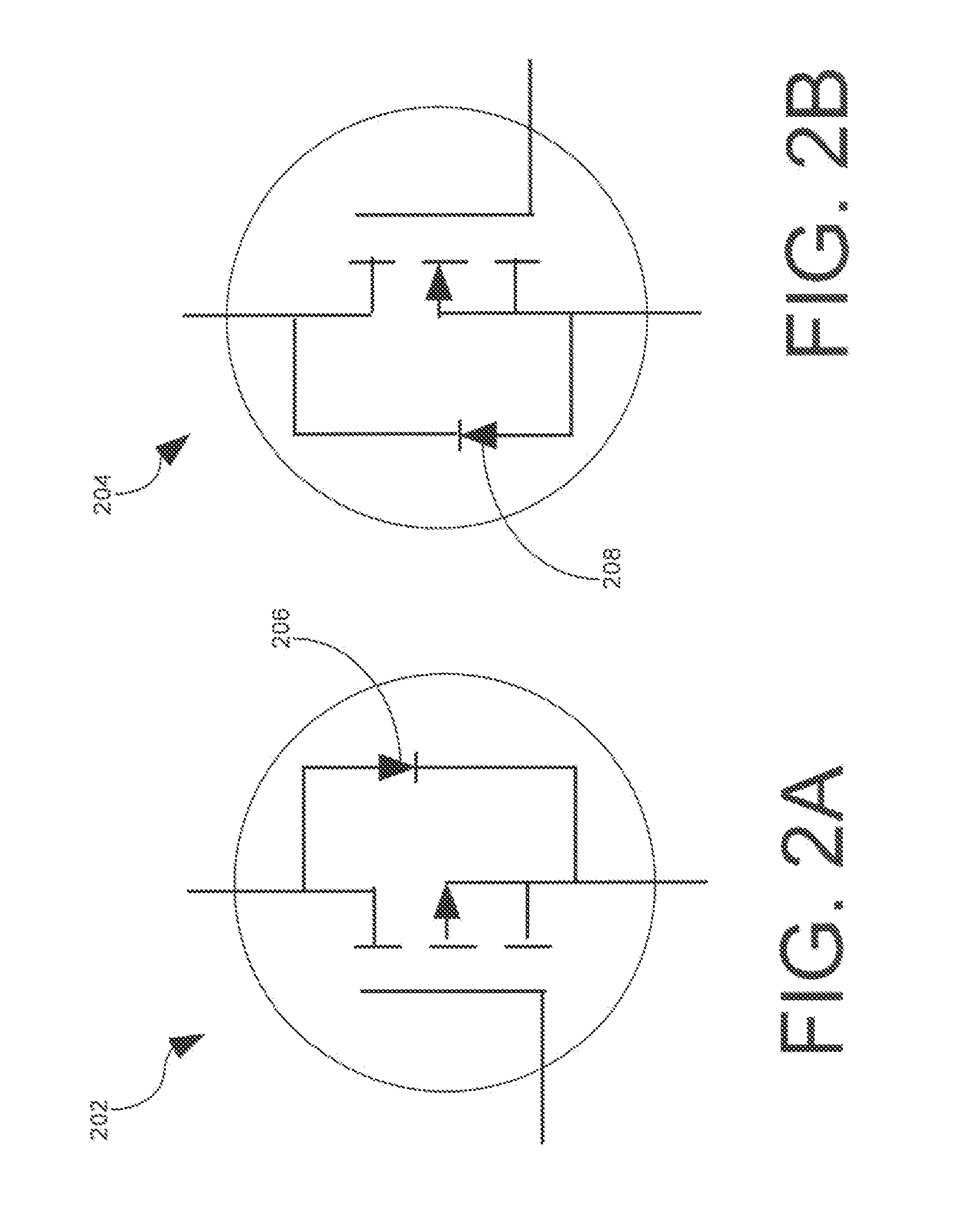
Figure 3
Abstract
Description
BACKGROUND OF THE INVENTION
[0001] 1. Statement of the Technical Field
[0002] The inventive arrangements relate to MOSFET circuits, and more particularly to a circuit for AC voltage rectification and shoot-through current protection.
[0003] 2. Description of the Related Art
[0004] Bridge rectifier type devices are typically used to convert an AC waveform into a DC waveform. Such bridge rectifier type devices often utilize diode components to perform the rectification function. After an AC signal is rectified, the output signal is often filtered to remove unwanted spectral content and to produce a DC voltage, A filtering device utilizing capacitor components, resistor components, and / or inductor components are typically used for this purpose.
[0005] Despite the various technologies known in the art, there remains a need for a MOSFET bridge rectifier type device that can rectify a domestic AC input (for example, 120V, 60 Hz) and / or a foreign AC input (for example, 230V, 50 Hz) with low power lo...