
Multiple wafer level multiple port register file cell

Inactive Publication Date: 2008-11-27
IBM CORP
View PDF1 Cites 47 Cited by
  • Summary
  • Abstract
  • Description
  • Claims
  • Application Information

AI Technical Summary

Benefits of technology

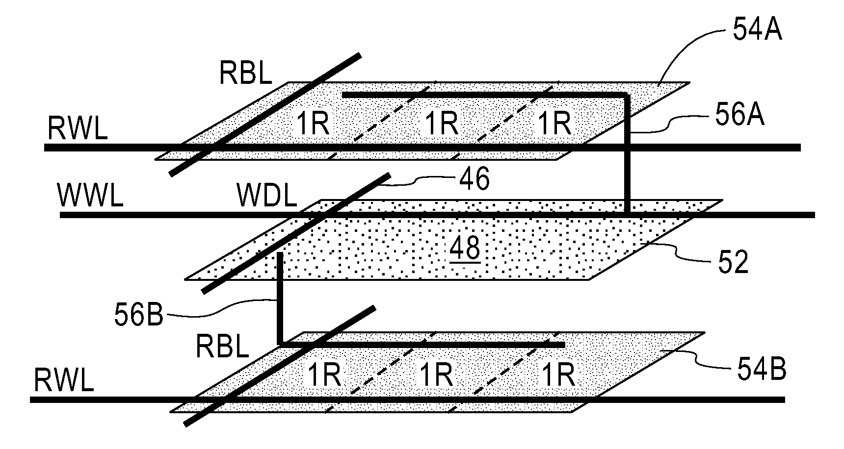
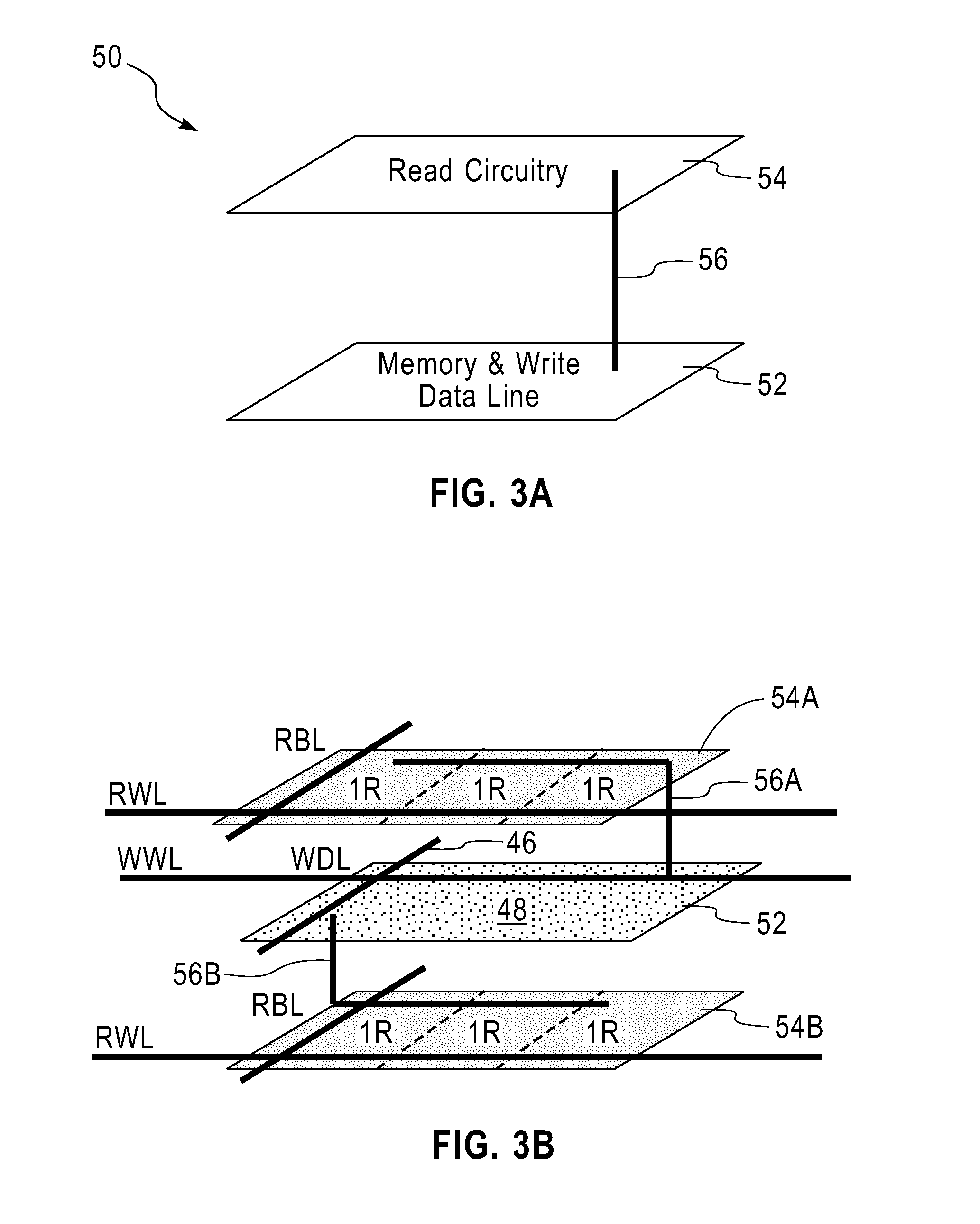
[0009]By vertically stacking multiple active circuit layers with vertically aligned interconnects, at least each read port of a multi-port register file can be implemented on a separate layer above or below the primary data storage cell. This allows the multi-port register file structure to be implemented within the same area footprint as a standard register file cell, minimizing data read and write delays. Each write data line and read data bitline has a length associated with a simple two-dimensional register file cell array.
[0010]The inventive three dimensional approach allows the interconnect delays of write data lines and read bitlines for a multi-port register file to be comparable to those associated with the bitlines of a conventional two dimensional one read, one write register array. The write data and read bitline access is improved over the standard two dimensional approach for multi-port register arrays. The base register file (storage node) layer can be identical to a standard register file, eliminating the need for additional reticle enhancement techniques to be developed for a register file cell.
[0018]In the aforementioned embodiment, each storage node (e.g., true and compare) of the storage element (i.e., latch component) is connected through one of the vertically filled via holes to the one of the wafers including the read data bitlines. For example, the true node can be connected to the at least one first read data-containing wafer by the first vertically filled conductive filled via hole, while the compare node can be connected to the at least one second read data-containing wafer by the second vertically filled conductive wafer. Such an arrangement tends to reduce the load on the true and compare nodes of the storage element.
[0019]To further reduce the load on the true and compare nodes of the storage element, a true / complement generator buffer layer can be formed above the storage cell to isolate the load of multiple read ports from the storage nodes. This embodiment of the present invention is particular useful for large multi-port arrays (e.g., arrays with 16 read ports and two write ports).

Problems solved by technology

As the complexity of microprocessors increase, the number of possible units and / or threads needing to access the GPR is increasing.
As microprocessor complexity and MOS transistor counts grow, designers are working hard to find ways to lower AC and DC power.
Such an arrangement would take up the wiring resources that are hard to come by for multi-port register files due to multiple wordlines and bitlines to the cell.

Method used


Image

  • Multiple wafer level multiple port register file cell
  • Multiple wafer level multiple port register file cell
  • Multiple wafer level multiple port register file cell

Examples


Embodiment Construction

[0032]The present invention, which provides a multi-port register file cell and a method of fabricating the same, will now be described in greater detail by referring to the following discussion and drawings that accompany the present application. It is noted that the drawings are provided for illustrative purposes only. As such, the drawings included within the present application are not drawn to scale.

[0033]In the following description, numerous specific details are set forth, such as particular structures, components, materials, dimensions, processing steps and techniques, in order to provide a thorough understanding of the present invention. However, it will be appreciated by one of ordinary skill in the art that the invention may be practiced without these specific details. In other instances, well-known structures or processing steps have not been described in detail in order to avoid obscuring the invention.

[0034]It will be understood that when an element as a layer, region ...


PUM


Abstract

A multi-port register file (e.g., memory element) is provided in which each read port of the register file is located in a separate wafer above and / or below the primary data storage element. This is achieved in the present invention by utilizing three-dimensional integration in which multiple active circuit layers are vertically stacked and vertically aligned interconnects are employed to connect a device from one of the stacked layers to another device in another stacked layer.

Description

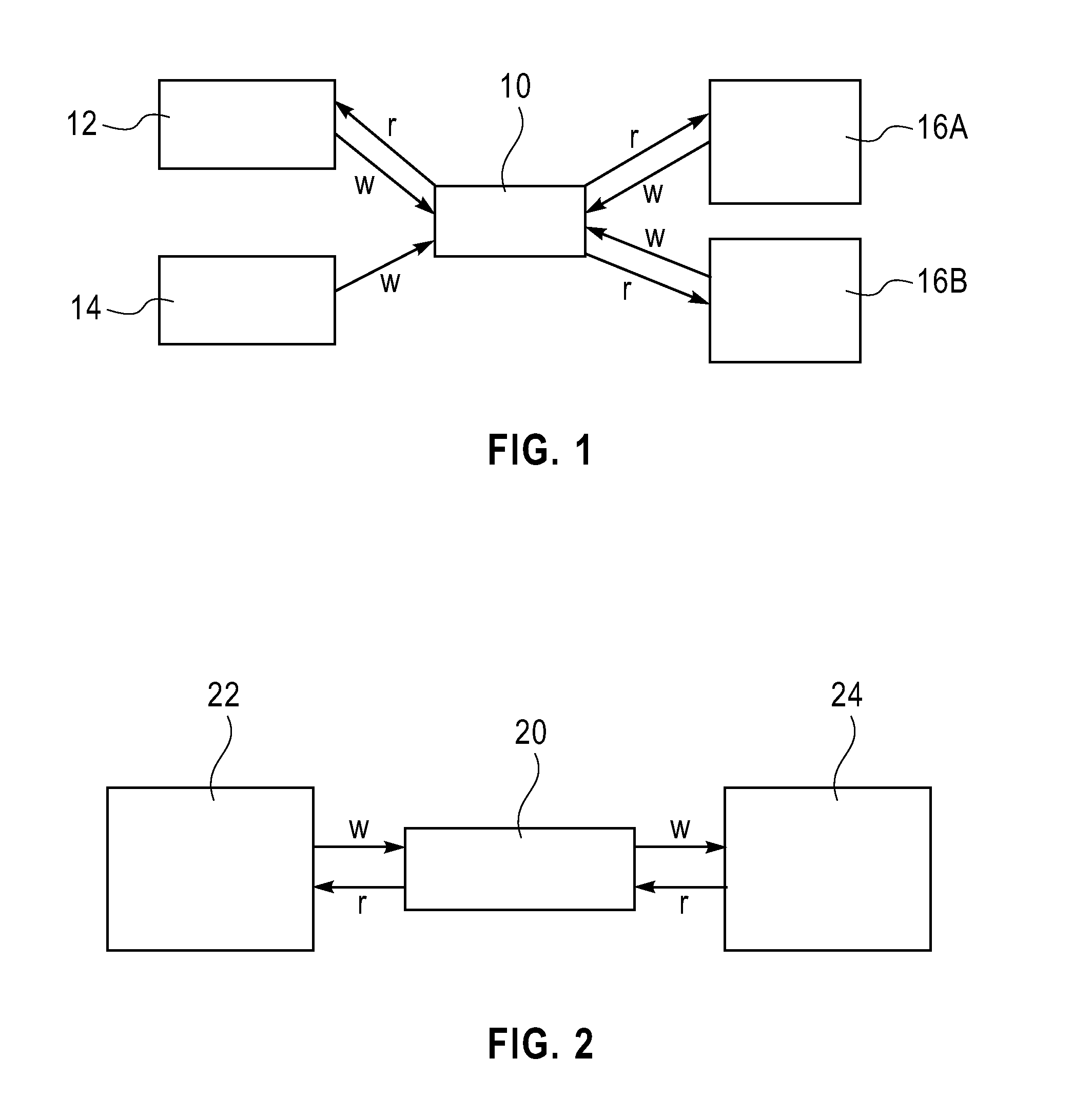
FIELD OF THE INVENTION[0001]The present invention relates to a semiconductor structure and a method of fabricating the same. More particularly, the present invention relates to a memory element that includes multiple write sources and read destinations.BACKGROUND OF THE INVENTION[0002]In modern microprocessors, multi-port register file cells (i.e., a memory element with multiple write sources and multiple read destinations) are used for many architectural elements. A common element that the multi-port register file is used for is the General Purpose Register (i.e., GPR). The GPR memory array is used to hold data that is being operated on by different instructions from a host of possible units (pieces of the microprocessor) and / or threads (multiple instruction pipes). This is illustratively shown in FIG. 1 in which reference numeral 10 denotes the GPR, reference numeral 12 denotes a floating point unit (FDU), reference numeral 14 denotes an instruction unit (IU) and reference numeral...

Claims


Application Information

Patent Timeline
IPC IPC(8): G11C8/00H01L21/4763
CPCH01L21/8221H01L21/84H01L27/0688H01L27/1203
Inventor BARNES, JOSEPH S.ATWAL, JAGREET S.BERNSTEIN, KERRYBUCKI, ROBERT J.
Owner IBM CORP
Learn More