
Inflatable devices and methods to protect aneurysmal wall

a technology of aneurysmal wall and inflatable device, which is applied in the field of inflatable device and method to protect aneurysmal wall, can solve the problems of unsuitable for all patients, risky procedure, and estimated 32,000 deaths resulting from aneurysmal rupture, so as to improve the surface area, improve the healing effect, and reverse the pathology

Inactive Publication Date: 2008-11-27
CHU JACK FA DE
View PDF16 Cites 61 Cited by
  • Summary
  • Abstract
  • Description
  • Claims
  • Application Information

AI Technical Summary

Benefits of technology

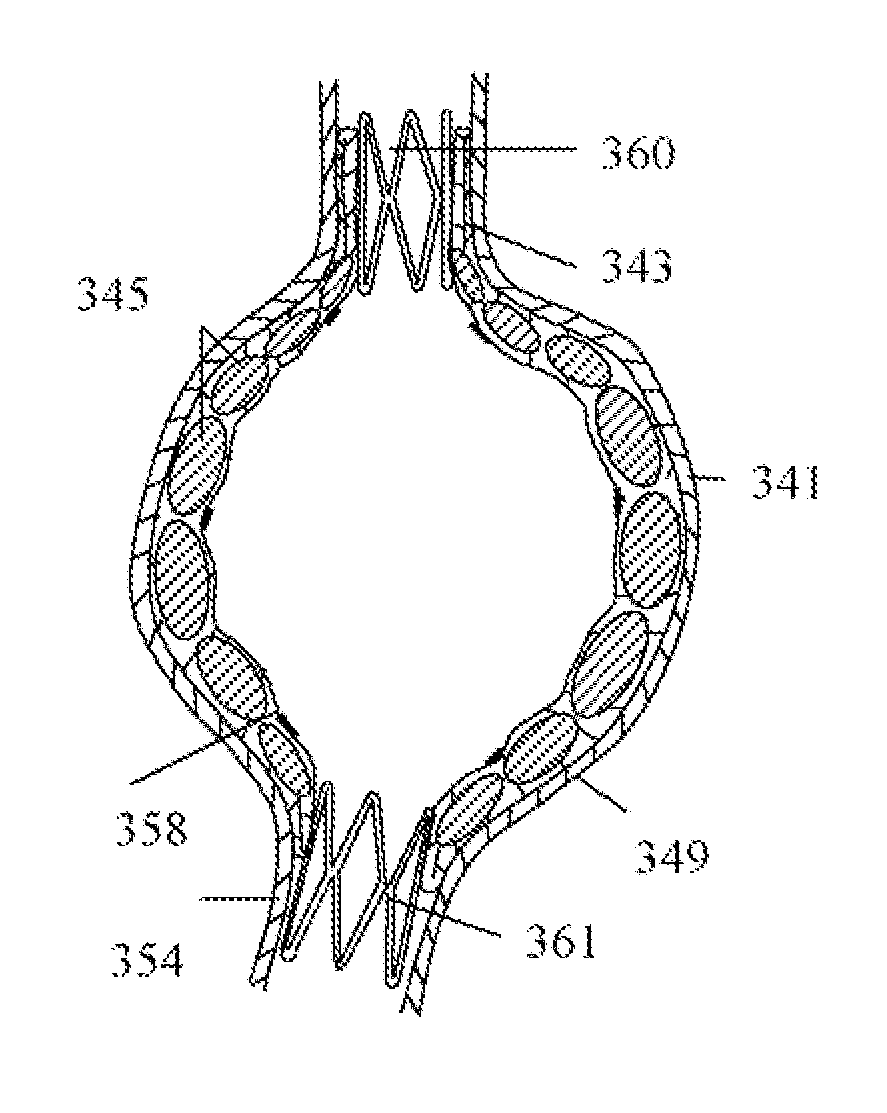
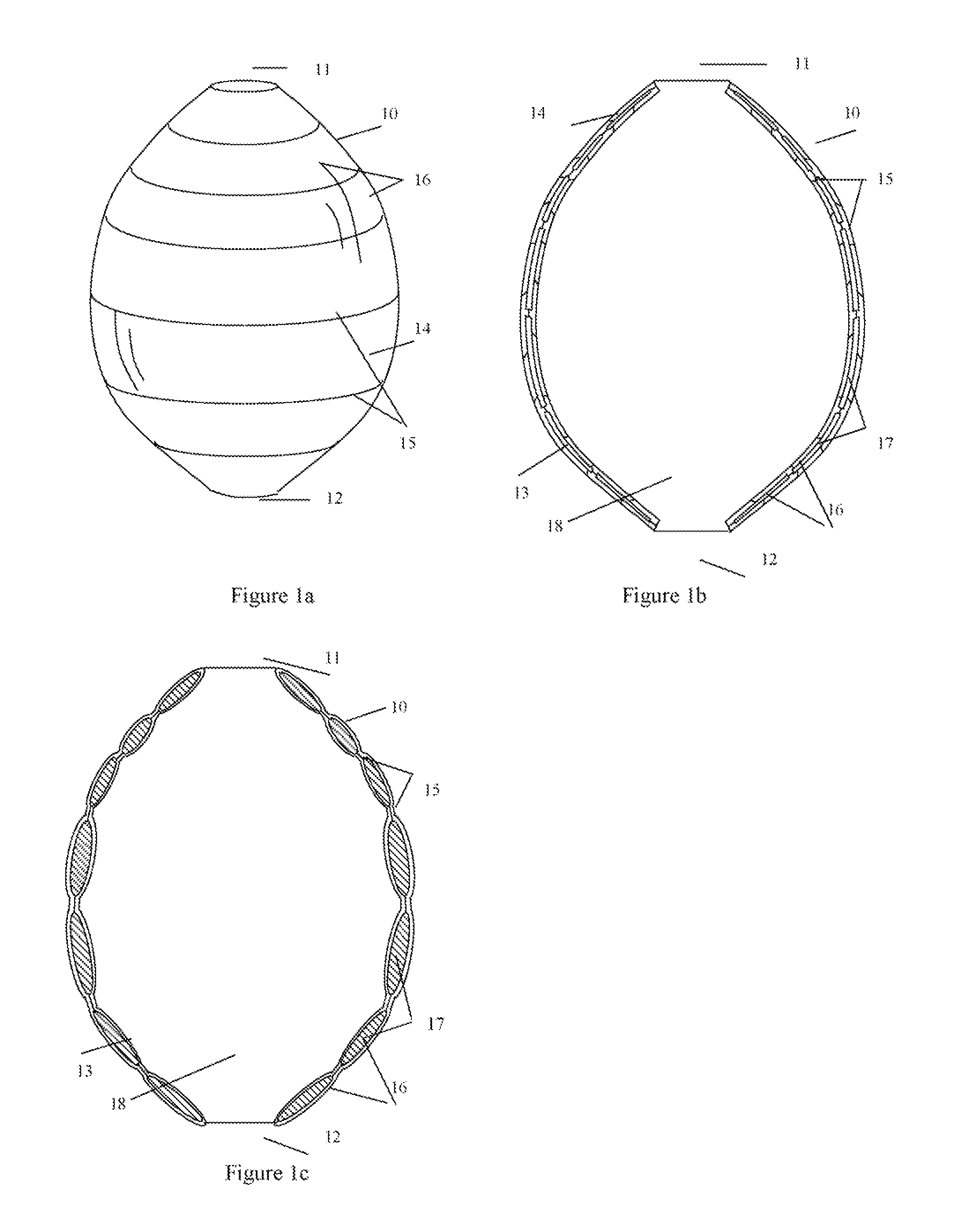
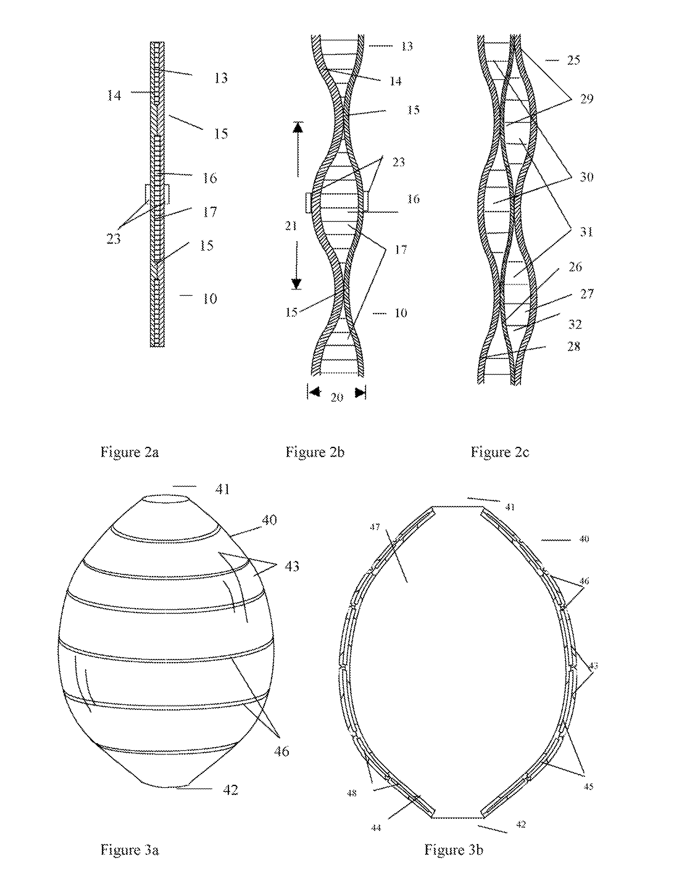
[0013]The present invention addresses the issues with the current therapies by providing methods and systems to reduce the likelihood of migration, endoleak and rupture at aneurysm sites. The systems comprise an inflatable liner which is larger or the same size as the aneurysm. The inflatable liner comprises an absorbent encapsulated between a flexible outer wall and a flexible inner wall. It has a pliable mode and a strengthening mode. In its pliable mode, this inflatable liner is flexible and can be loaded into a catheter. After the liner is introduced in the aneurysm, the liner expands and conforms to the surface of the aneurysm wall. The conformation of the liner to the aneurysm wall is achieved by the flexible walls and a hemodynamic force. During the inflation of the liner, the outer wall of the liner remains in close contact with the aneurysm wall. The body fluid permeates through the flexible walls and activates the absorbent in the liner. The activated absorbent absorbs body fluid and expands the thickness of the liner. Because the outer wall is still in contact with the aneurysm wall, the inner wall of the liner moves away from the inner surface of the aneurysm in a restrained fashion by the connectors between the walls and defines the flow conduit. After deploying in the aneurysm, the body fluid transforms the liner from the pliable mode to the strengthening mode to support the aneurysm wall. The resulting strengthened liner is “locked” in the ancurysm with minimum chance to migrate out of its designated location.
[0014]In another embodiment of this invention, the inflatable liner has encapsulated absorbent that expands in large volume after picking up body fluid in the aneurysm. Many suitable absorbent can be used in the liner. The preferable absorbent is a hydrogel or a hydrophilic material which can absorb a large volume of body fluid after it is in contact with the body fluid. The absorbent can be laminated between two flexible walls by spraying, coating, dipping on the walls and dried. At least one wall of the inflatable liner is permeable to the body fluid. Before the absorbent is activated by the body fluid and expanding, the absorbent is flexible and enhances the flexibility of the inflatable liner. After the liner is deployed in the aneurysm, the body fluid passes through the wall and enables the absorbent to expand. The expanded absorbent pushes the walls outward and thus thickening and strengthening the liner. After this transformation from pliable mode to strengthening mode, the inflated liner locked in the aneurysm providing reinforcement to the aneurysm wall.
[0015]In another embodiment of this invention, inflatable liner can be fabricated with many methods. Inflatable liner can be made by joining two flexible pouch shape walls together. The space between the walls defines at least one inflatable chamber to be filled by the absorbent. Each wall can be made from the same or different material. The walls are connected by a stripe, a string or a bond, such as glue bond, weld bond, heat bond, etc. at a plurality of locations between the walls. The material used for the connector should have a significant inelasticity to avoid excess stretching during inflating. The extent of the connection can be a single point, an area, a line, or a dotted line. Combined with the walls, the arrangement and the type of connector define the inflatable chamber and are important for the flexibility of the liner. If the span of the connector between the walls is long, the liner is thick with a lower flexibility after inflation. On the other hand, if the span of the connector is short, the liner is thin with a higher flexibility at the connector. It is preferable that the liner is relatively thinner near the opening of the flow conduit to increase its flexibility to comply with patient's anatomy near the opening for optimum seal. On the other hand, the inflatable liner can be thicker in the middle of the aneurysm for additional strength and aneurysm protection.

Problems solved by technology

These weakened sections of vessel walls can rupture, causing an estimated 32,000 deaths in the United States each year.
Additionally, deaths resulting from aneurysmal rupture are suspected of being underreported because sudden unexplained deaths are often misdiagnosed as heart attacks or strokes while many of them may in fact be due to ruptured aneurysms.
However, this procedure was risky and not suitable for all patients.
Patients who were not candidates for this procedure remained untreated and thus at risk for aneurysm rupture or death.
While tubular stent grafts represent improvements over more invasive surgery procedures, there are still risks associated with their use to treat aneurysms.
This vulnerable aneurysm sac is also prone to endoleak.
Stent graft migration is especially common in aneurysms with short neck where there is insufficient overlap between the stent graft and the vessel, and in tortuous portions of the vessels where stent graft tends to kink resulting high hemodynamic forces on the stent graft.
Stent graft migration can break the seal between the tubular stent graft and vessel and lead to Type I endoleak, or the leaking of blood into the aneurismal sac between the outer surface of the stent graft and the inner surface of the blood vessel.
This endoleak can result in the aneurysm wall being exposed to hemodynamic pressure again, thus increasing the risk of rupture.
The patent collateral arteries (inferior mesenteric artery, lumbar artery) in the aneurismal sac can lead to an increased pressure in the aneurysm and may cause aneurysm enlargement and rupture in some patients.
Both follow-up procedures and secondary interventions are undesirable because the cost and the risk involved in those procedures.
While these physical anchoring devices have proven to be effective in some patients, tubular stent grafts are still prone to kink.
However, embolization agent or dislodged emboli can travel downstream and embolize small vessels in the legs or colon.
However, the junctions to the collateral vessels in the aneurismal sac are not protected.
Unfortunately, it is very difficult to identify the patency of the collateral vessels (inferior mesenteric artery, lumbar artery) in the aneurismal sac by the current imaging techniques, such as CT or MRI.
If those collateral vessels are patent, i.e. a Type II endoleak is diagnosed, there is a risk that the injected embolization agent or dislodged emboli will migrate into those collateral vessels and embolize important vessels in the lumbar and colon.
However, there are several concerns with this approach.
However, the gap between the fill structure and the aneurysm wall cannot be visualized easily (no contrast agent in gap or aneurysm wall) under Fluoroscope during the inflation of the fill structure, physician cannot determine if the gap has been filled (or not being filled) by the fill structure.
This uncertainty can cause excess amount of filler in the fill structure and consequently high stress on the aneurysm wall and place the patient in great risk.
Existing blood in the aneurysm (with the added filler) can also cause high stress on the aneurysm wall during the inflation of fill structure if the collateral arteries in the aneurysm are occluded.
Third, a significant amount of filler is required to fill the aneurismal sac for patients with large aneurysms.

Method used


Image

  • Inflatable devices and methods to protect aneurysmal wall
  • Inflatable devices and methods to protect aneurysmal wall
  • Inflatable devices and methods to protect aneurysmal wall

Examples


Embodiment Construction

[0054]Embodiments according to the present invention provide inflatable liner and methods useful for protecting aneurysm and reducing the risk of implantable medical device post-implantation migration and endoleak. More specifically, the inflatable liner and methods provide protection to blood vessel against rupture especially at the aneurysm site. The inflatable liner also has the advantage of no kinking, minimizing post-implantation device migration and endoleak following liner deployment at an aneurismal site.

[0055]For convenience, the devices, compositions and related methods according to the present invention discussed herein will be exemplified by using inflatable multiple walls liner intended to treat abdominal aorta aneurysms or Thoracic aortic aneurysms. However, aneurysms at other locations of the body can be treated with the same devices or methods.

[0056]The present invention addresses the issues with current therapies by providing methods and systems to reduce the likeli...


PUM


Abstract

Methods and systems for preventing aneurysm rupture and reducing the risk of migration and endoleak are disclosed. Specifically, an inflatable liner is applied directly to treat the interior of the aneurysm site. Also disclosed are methods to deliver the inflatable liner directly to treatment sites.

Description

[0001]This application claims the benefit of U.S. Provisional Application No. 60 / 910,148, which was filed Apr. 4, 2007, the disclosure of which is incorporated herein by this reference.FIELD OF THE INVENTION[0002]Methods and devices for preventing rupture of an aneurysm and reducing the risk of endoleak are disclosed. Specifically, methods and systems for applying inflatable multiple-layer liners directly to treatment sites and to the interior of the vessel wall are provided.BACKGROUND OF THE INVENTION[0003]An aneurysm is a localized dilation of a blood vessel wall usually caused by degeneration of the vessel wall. These weakened sections of vessel walls can rupture, causing an estimated 32,000 deaths in the United States each year. Additionally, deaths resulting from aneurysmal rupture are suspected of being underreported because sudden unexplained deaths are often misdiagnosed as heart attacks or strokes while many of them may in fact be due to ruptured aneurysms.[0004]Approximate...

Claims


Application Information

Patent Timeline
Patent Type & Authority Applications(United States)
IPC IPC(8): A61F2/82
CPCA61F2/07A61F2002/077A61F2/89A61F2002/072A61F2002/075A61F2230/0071
Inventor CHU, JACK FA-DE
Owner CHU JACK FA DE
Learn More