Planar resonator gyroscope central die attachment

Active Publication Date: 2008-12-04
THE BOEING CO
View PDF11 Cites 38 Cited by
  • Summary
  • Abstract
  • Description
  • Claims
  • Application Information

AI Technical Summary

Benefits of technology

[0015]Packaging techniques for planar resonator gyroscopes, such as disc resonator gyroscopes (DRGs) are disclosed. A gyroscope die may be attached to its package substrate on a central disc area that is inboard of its embedded electrodes. This configuration eliminates contact of the die with the package substrate beneath the embedded electrodes allowing the internal electrode support structure to expand or contract freely without stress as its temperature changes, thus avoiding stress that would induce gap nonuniformity. A symmetric and highly conductive isothermal disc attachment area to a symmetric baseplate and resonator ensures symmetric spread of heat from the package substrate and resulting sy

Problems solved by technology

Residual temperature gradients across the resonator also

Method used


Image

  • Planar resonator gyroscope central die attachment
  • Planar resonator gyroscope central die attachment
  • Planar resonator gyroscope central die attachment

Examples


Example

1. Overview

[0030]In the following description including the preferred embodiment, reference is made to the accompanying drawings which form a part hereof, and in which is shown by way of illustration a specific embodiment in which the invention may be practiced. It is to be understood that other embodiments may be utilized and structural changes may be made without departing from the scope of the present invention.

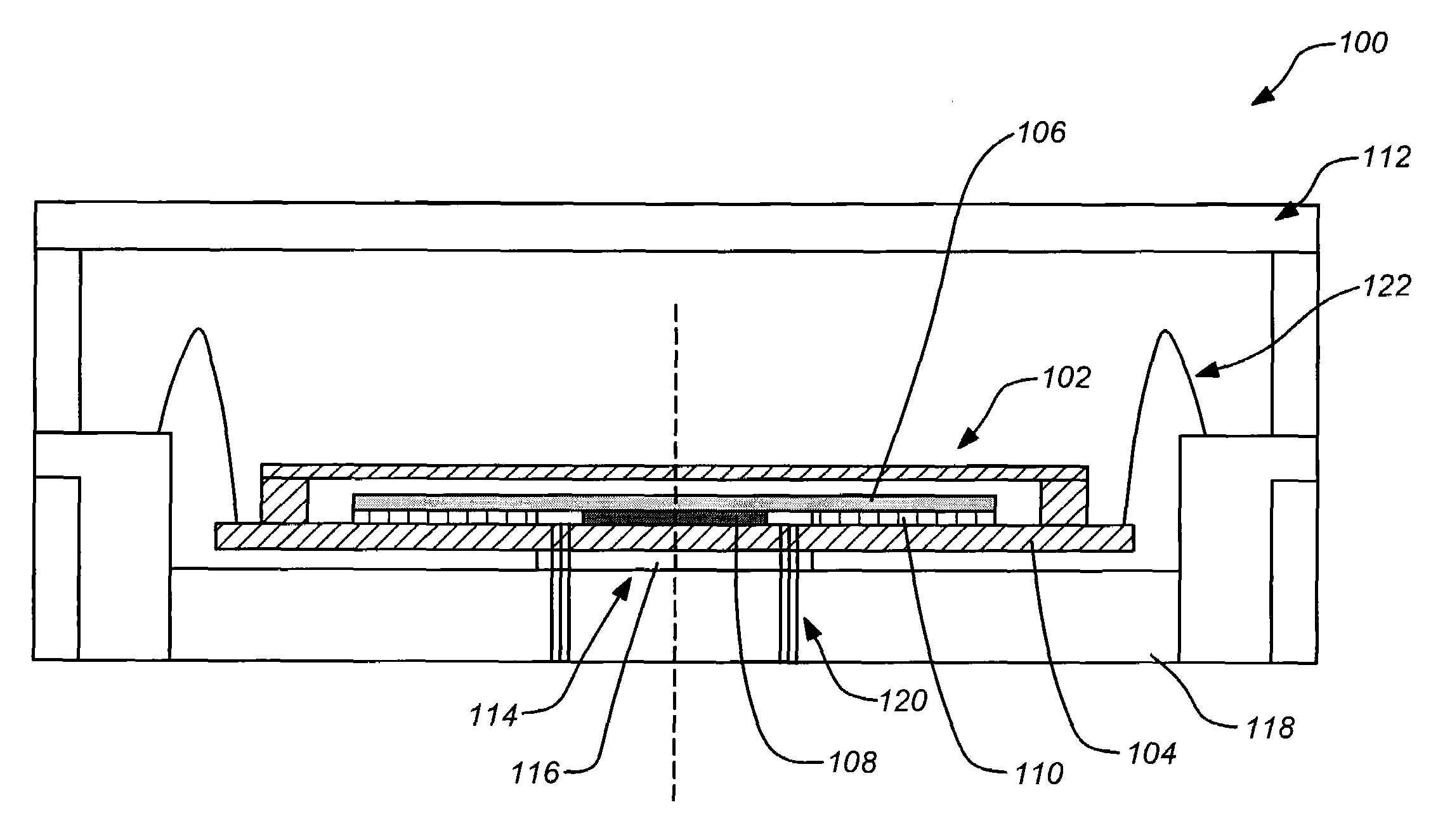
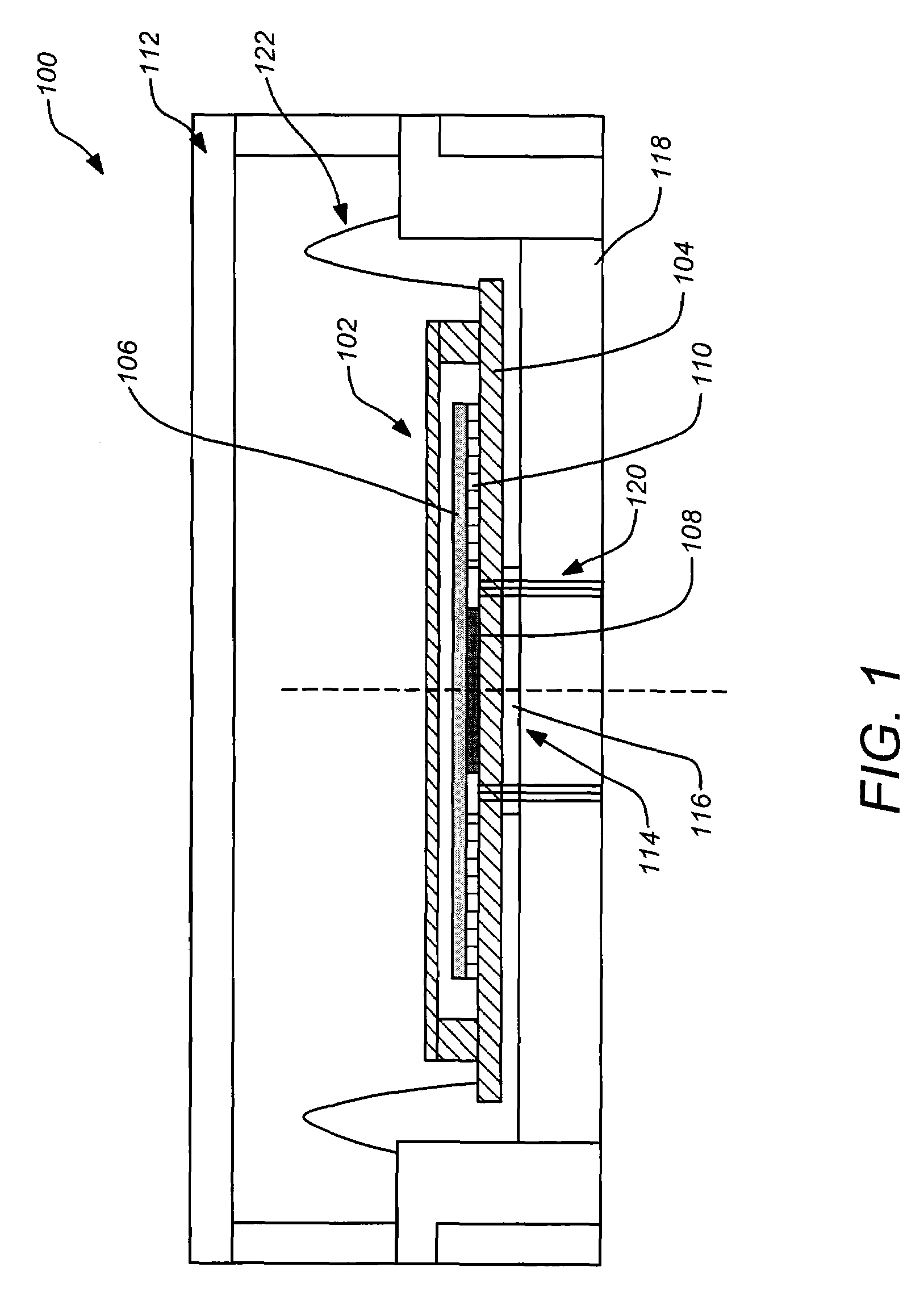
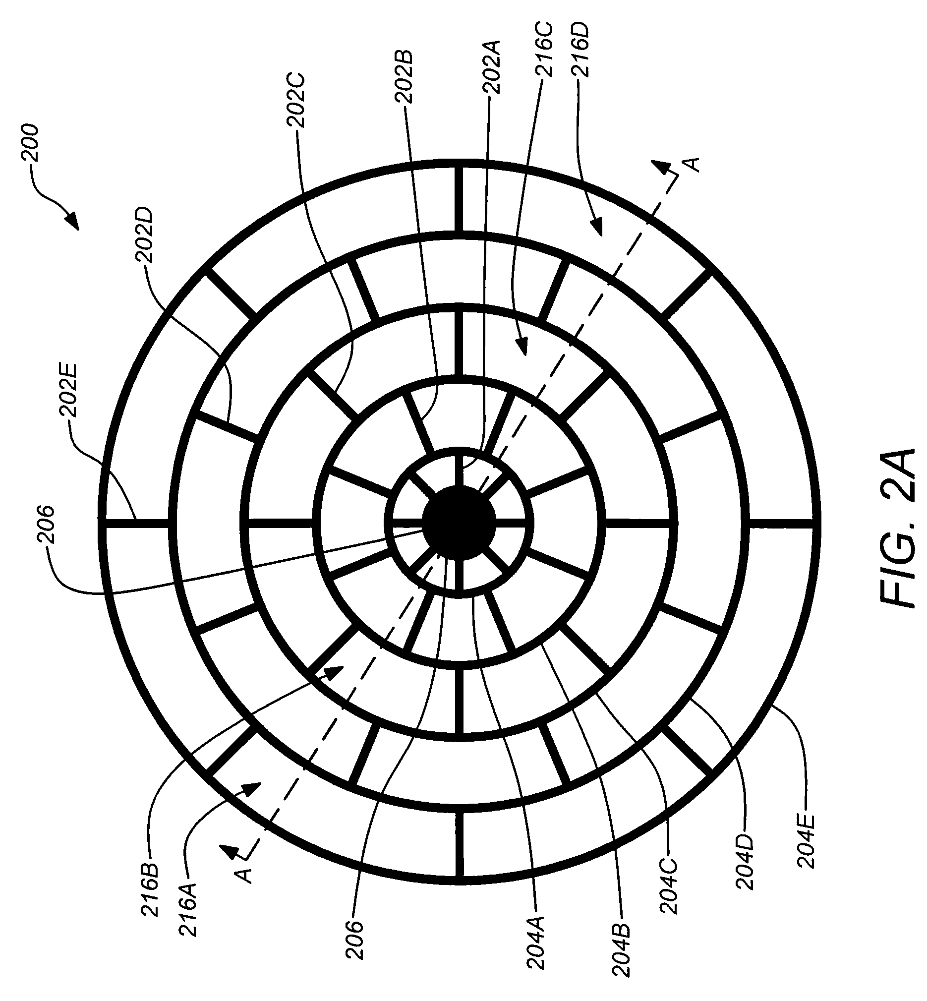
[0031]Embodiments of the invention may be directed to packaging a planar resonator gyroscope such that a gyroscope die is attached to its package substrate on a central disc area that is inboard of its electrodes. A circular or symmetric disc having at least 8-fold symmetry may be preferred. This configuration can eliminate contact of the die with the package substrate in the area beneath the electrodes. This allows the internal electrode support structure to expand or contract freely without any stress as its temperature changes, thus avoiding stress that would induce gap...


PUM


Abstract

Packaging techniques for planar resonator gyroscopes, such as disc resonator gyroscopes (DRGs) are disclosed. A gyroscope die may be attached to its package substrate on a central disc area that is inboard of its embedded electrodes. This configuration eliminates contact of the die with the package substrate beneath the embedded electrodes allowing the internal electrode support structure to expand or contract freely without stress as its temperature changes. The central attachment can also be used diminish the package temperature gradients on the periphery of the die, if the thermal conductivity of the central disc attachment material is higher than the package substrate. Temperature gradients across the resonator also lead to thermoelastic damping asymmetry and rate drift. In addition, the electrical connections to the die may be formed by vertical vias within the central disc attachment area or by thin wirebonds to peripheral I/O pads on the gyro chip.

Description

CROSS-REFERENCE TO RELATED APPLICATIONS[0001]This application is related to the following co-pending patent applications, which are both incorporated by reference herein:[0002]U.S. patent application Ser. No. 11 / 371,596, filed Mar. 9, 2006, and entitled “ISOLATED PLANAR RESONATOR GYROSCOPE WITH INTERNAL RADIAL SENSING AND ACTUATION”, by Kirill V. Shcheglov et al.; and[0003]U.S. patent application Ser. No. 11 / 199,004, filed Aug. 8, 2005, and entitled “INTEGRAL RESONATOR GYROSCOPE”, by Kirill V. Shcheglov et al.BACKGROUND OF THE INVENTION[0004]1. Field of the Invention[0005]The present invention relates to gyroscopes, and in particular to planar resonator gyroscopes or inertial sensors and their manufacturing. More particularly, this invention relates to the packaging of isolated planar resonator inertial sensors and gyroscopes.[0006]2. Description of the Related Art[0007]Mechanical gyroscopes are used to determine direction of a moving platform based upon the sensed inertial reaction...

Claims


Application Information

Patent Timeline
IPC IPC(8): G01C19/28
CPCY10T74/1275G01C19/5684
Inventor CHALLONER, A. DORIAN
Owner THE BOEING CO
Why Eureka
Try Eureka