Film Dispersed of Carbon Nanotubes and Light Emitting Body

Inactive Publication Date: 2008-12-04
KONICA MINOLTA INC +1
View PDF3 Cites 14 Cited by
  • Summary
  • Abstract
  • Description
  • Claims
  • Application Information

AI Technical Summary

Benefits of technology

[0023]According to the first invention, since each carbon nanotube is dispersed isolatedly in an oriented manner, it can absorb excitation light with a particular wavelength and emit intensive light with a particular wavelength.
[0024]According to the second invention, since film dispersed of carbon nanotubes according to the first invention is supported on the substrate, rigidity is high, and thus application to various field is eased.
[0025]According to the third invention, since the carb

Problems solved by technology

Therefore, even though excitation light is irradiated to the thin film, light with a particular wavelengt

Method used


Image

  • Film Dispersed of Carbon Nanotubes and Light Emitting Body
  • Film Dispersed of Carbon Nanotubes and Light Emitting Body
  • Film Dispersed of Carbon Nanotubes and Light Emitting Body

Examples


first embodiment

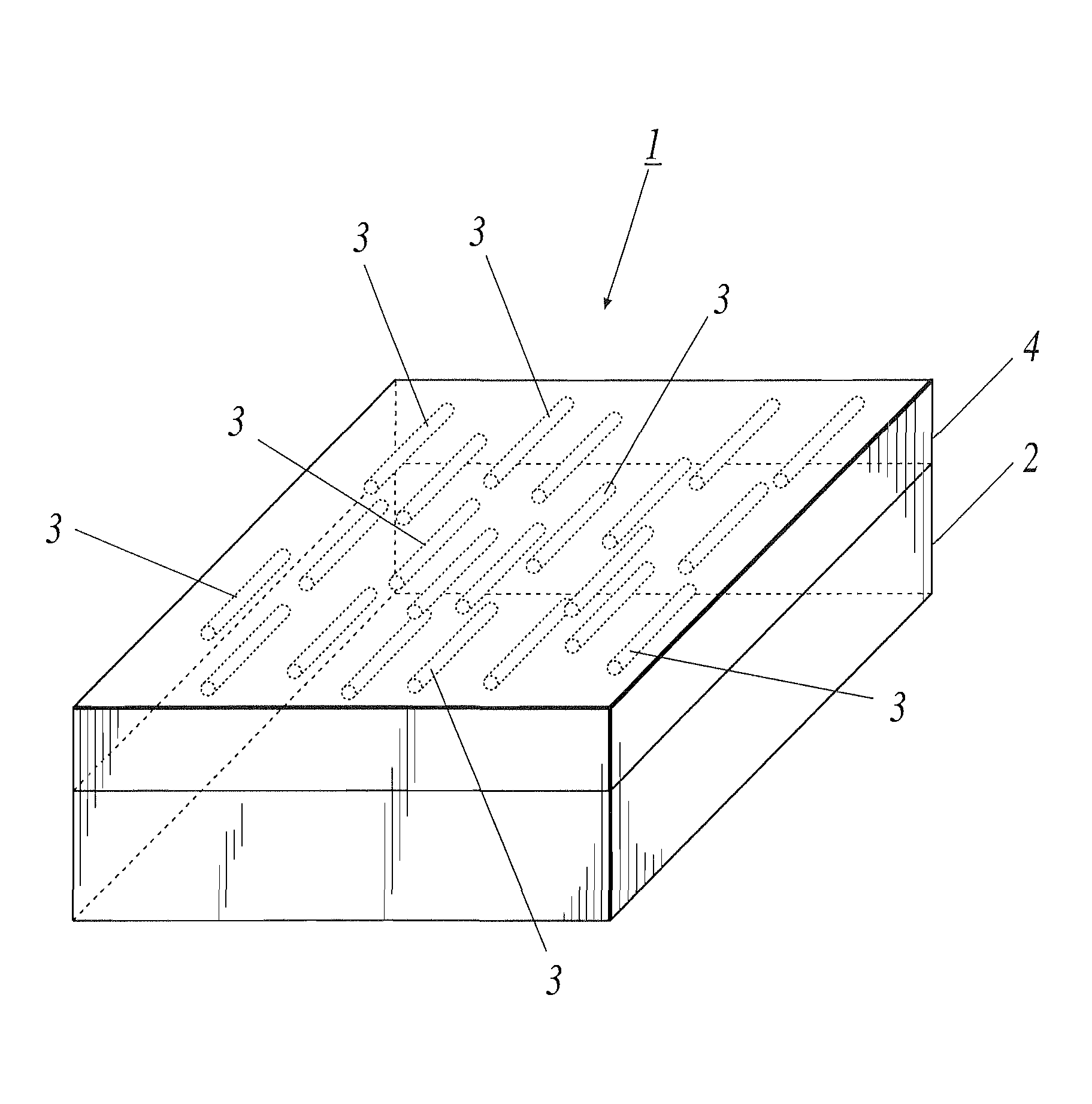
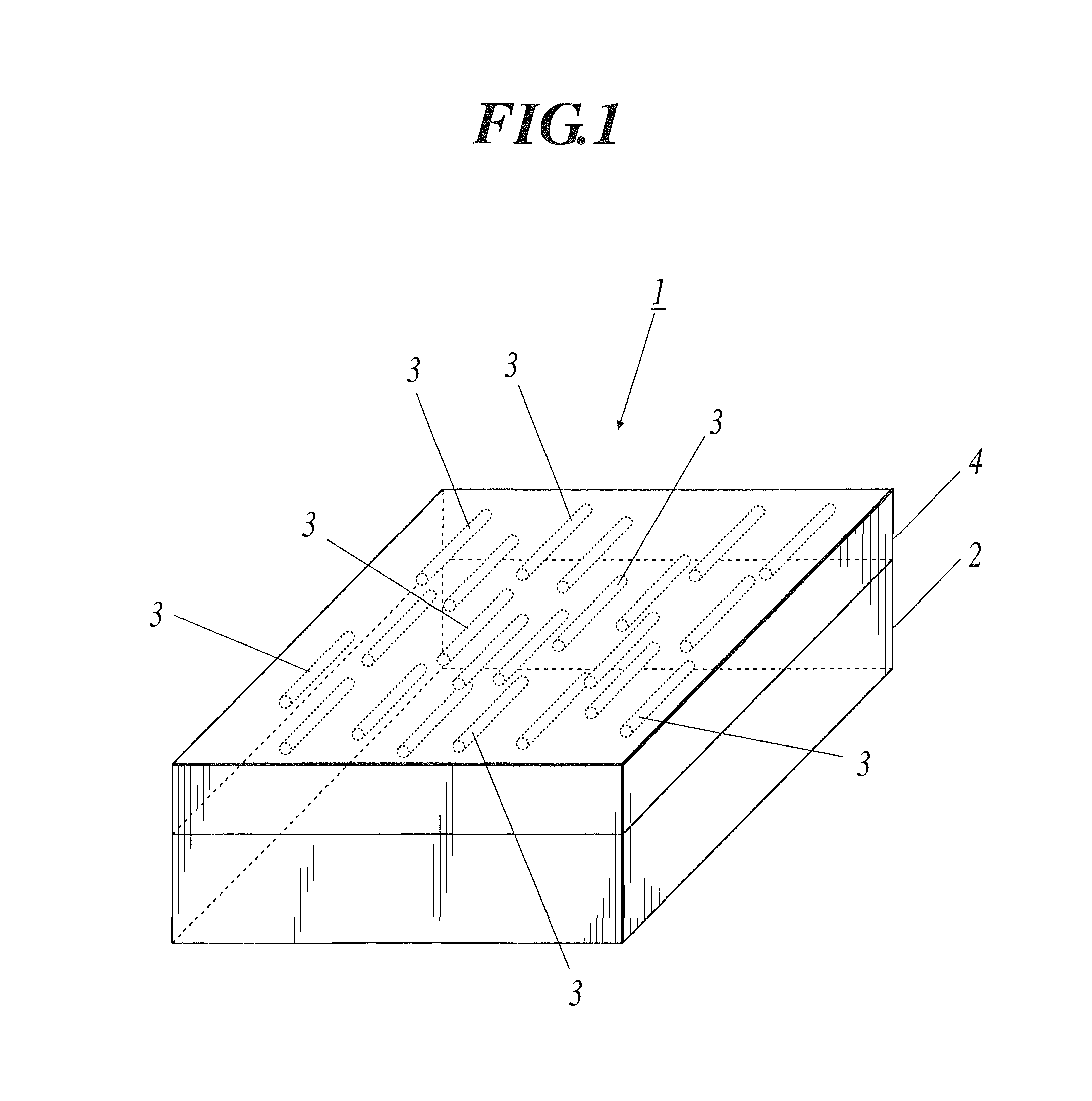
[0033]FIG. 1 is a perspective view showing a schematic structure of light emitting body 1 according to the first embodiment.

[0034]As shown in FIG. 1, the light emitting body 1 is provided with a substrate 2 that has a rectangular shape. A film dispersed of carbon nanotubes 4 which has a plurality of carbon nanotubes 3, 3, . . . dispersed is formed on the substrate 2.

[0035]As for the substrate 2, material with any property among insulating property, conductive property, and semi-conductive property can be applied. For example, materials such as quartz, glass, quartz glass, ceramics, metal, silicone, and the like can be used. In a case where the substrate 2 is structured with glass, it is preferable to use transparent glass such as soda-lime glass, low soda glass, lead-alkali-silicate glass, borosilicate glass, and the like. In particular, it is preferable to structure the substrate 2 with a high strain point low soda glass and low soda glass. In a case where the substrate 2 is struct...

second embodiment

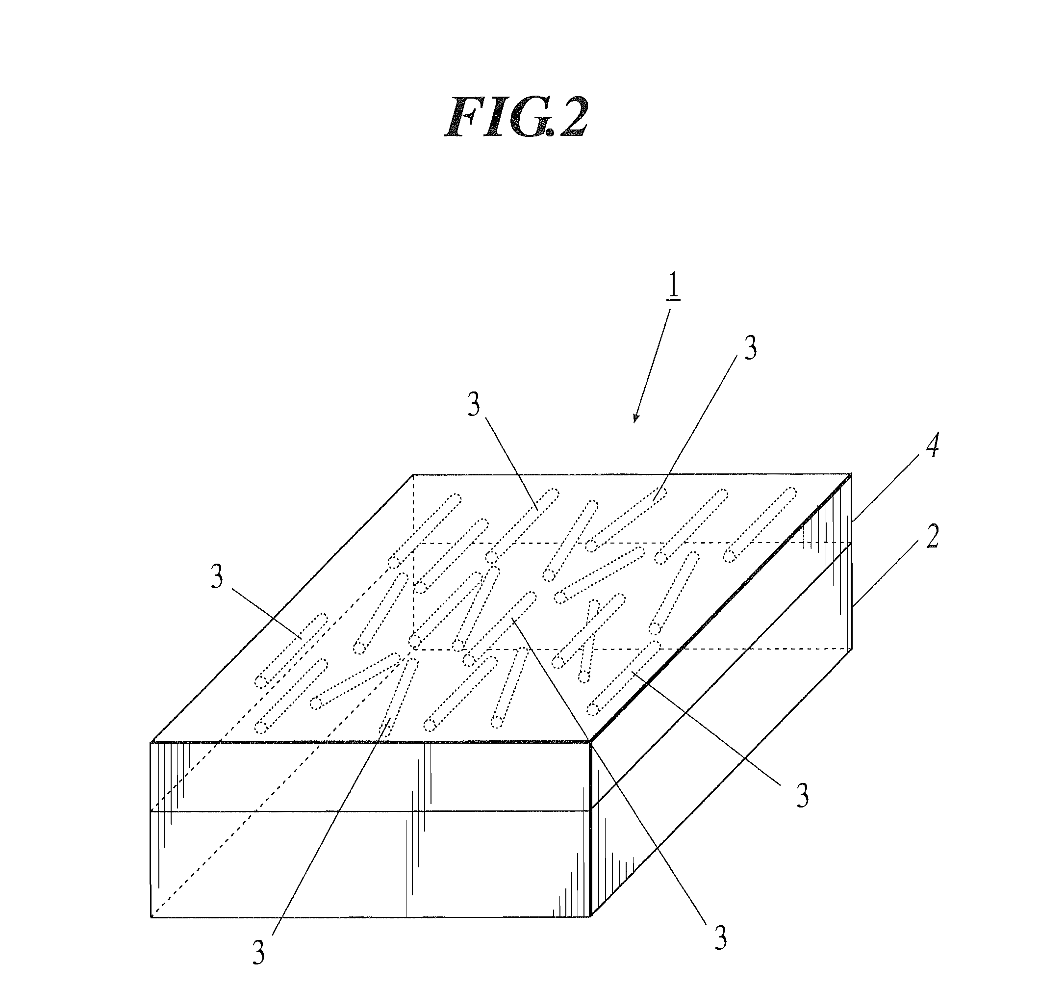
[0079]FIG. 2 is a perspective view showing a schematic structure of a light emitting body according to the second embodiment.

[0080]As shown in FIG. 2, the light emitting body 1 according the second embodiment differs from the light emitting body 1 according to the first embodiment, concerning the state of each carbon nanotube 3 in the film dispersed of carbon nanotubes 4. Other structure is the same as the first embodiment. That is, concerning the light emitting body 1 shown in FIG. 2, each carbon nanotube 3 is only dispersed isolatedly (in an isolated state) in the film dispersed of carbon nanotubes 4, and each carbon nanotube 3 is not oriented in a certain direction.

[0081]The manufacturing method of light emitting body 1 and the film dispersed of carbon nanotubes 4 according to the second embodiment are different from the manufacturing method of light emitting body 1 and the film dispersed of carbon nanotubes 4 according to the first embodiment in only a few steps, and other steps...

example 1

(1) Preparation of Test Sample A

[0085]To a D2O solution which was prepared by adding 100 mg of SDS to 10 g of D2O, 15 mg of known single-walled carbon nanotube formed by HiPco method was added to obtain HiPco containing solution. After the HiPco containing solution was obtained, ultrasonic processing was applied to the HiPco containing solution by a horn sonicator, for one hour within water-cooling at 10-15 degrees Celsius with output of 400 W.

[0086]After the ultrasonic dispersion processing was concluded, ultracentrifuge processing was applied to the HiPco containing solution after ultrasonic dispersion processing, with 330,000 g (plus minus 50,000 g) of load under 22 degrees Celsius for one hour. After the ultracentrifuge processing was concluded, upper 30% and lower 30% (including precipitation) was eliminated from the clear upper portion of the HiPco containing solution after ultracentrifuge processing, and the central 40% of the clear upper portion was collected to obtain HiPco...


PUM


Abstract

Disclosed is a film dispersed of carbon nanotubes that emits intensive light with a particular wavelength.
The film dispersed of carbon nanotubes 4 according to the present invention is a film in which a plurality of carbon nanotubes 3, 3, . . . are dispersed in the film dispersed of carbon nanotubes, and each carbon nanotube 3 is dispersed isolatedly in an oriented manner.

Description

FIELD OF THE INVENTION[0001]The present invention relates to a film dispersed of carbon nanotubes in which a plurality of carbon nanotubes are dispersed in a transparent binder, and a light emitting body using the same.DESCRIPTION OF THE BACKGROUND[0002]In the end of 20th century, C60 and carbon nanotube were added to the conventional carbon material, and thus “carbon” atom of IVB group structures the most various class of substance in the periodic table. As a substance that leads nanotechnology, which is assumed to be fundamental technology of the 21st century, cylinder of carbon, that is, “carbon nanotube”, is recently receiving high expectation. Variability in structures and functions of carbon material is derived from that the carbon atom takes bonding forms of sp, sp2, and sp3. This is a distinct characteristics of the carbon atom and differs largely from other atoms in the same IVB group, such as silicon and germanium. This variability in bonding forms is the root of the uniqu...

Claims


Application Information

Patent Timeline
IPC IPC(8): H01J1/02G11B5/64
CPCB82Y30/00
Inventor MARUYAMA, SHIGEOMIYAUCHI, YUHEIKONDO, YOSHIKAZUSAITO, ATSUSHI
Owner KONICA MINOLTA INC
Why Eureka
Try Eureka