

Non-aqueous air battery and catalyst therefor
- Summary
- Abstract
- Description
- Claims
- Application Information
AI Technical Summary
Benefits of technology
Problems solved by technology
Method used
Image

Examples
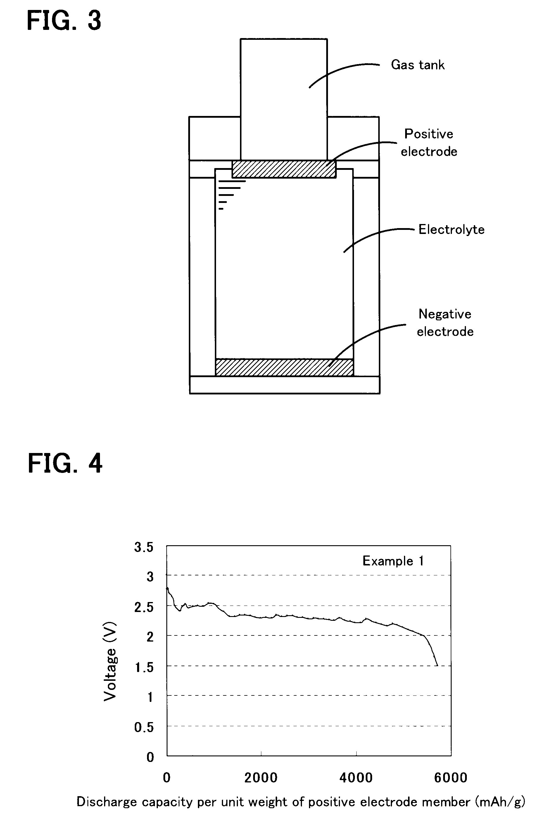
example 1
[0028]As a donor-acceptor molecule, triphenylporphyrinyl bithienyl N-methylpyrrolidino[60]fullerene (refer to Chemical Formula 1 below) in which triphenylporphyrin is connected to fullerene C60 having a fused pyrrolidine ring, with bithiophene therebetween was synthesized as follows. Specifically, first, 100 mg of fullerene C60 (manufactured by Aldrich) was dissolved in 100 mL of toluene at room temperature. The mixture was transferred to a 200-mL three-necked flask equipped with a dropping funnel, a condenser, and an argon inlet tube. Subsequently, 24.8 mg of N-methyl glycine (manufactured by Aldrich) was added to the solution. Furthermore, 10 mL of a dimethylformamide (DMF) solution containing 488 mg of triphenylporphyrinyl bithiophene aldehyde was added dropwise from the dropping funnel. Immediately after the completion of the dropwise addition, the reaction mixture was heated to reflux toluene, thus performing a reaction. After the reflux was performed for 15 hours, toluene and ...
example 2
[0034]A non-aqueous air battery was assembled as in Example 1 except that triphenylporphyrinyl bithienyl N-methylpyrrolidino[60]fullerene diethyl ester represented by Chemical Formula 2 was used instead of triphenylporphyrinyl bithienyl N-methylpyrrolidino[60]fullerene (refer to Chemical Formula 1) used in Example 1. Subsequently, 0.1 mA of current was supplied between the positive electrode and the negative electrode of this non-aqueous air battery, and discharge was performed until the open circuit voltage was decreased to 2 V. According to the result, the discharge capacity per unit weight of the positive electrode member was 4,065 mAh / g (refer to FIG. 6).
[0035]The compound represented by Chemical Formula 2 was prepared by using diethyl ester of fullerene C60 instead of fullerene C60 used in Example 1. Diethyl ester of fullerene C60 was synthesized in accordance with a known method (Chemische Berichte, Vol. 126, pp. 1957-1959, 1993). More specifically, first, 210 mg of fullerene ...
example 3
[0036]A non-aqueous air battery was produced as in Example 1 except that a nickel mesh (manufactured by Nilaco Corporation) was used instead of the stainless mesh. The measured discharge capacity per unit weight of the positive electrode member of this non-aqueous air battery was 14,560 mAh / g. This result showed that when donor-acceptor molecules were used in combination with nickel, the discharge capacity was markedly increased compared with the case where the donor-acceptor molecules were not used in combination with nickel (Example 1).
PUM
 Abstract
Description
Claims
Application Information