
Precision flexible current sensor

a flexible current and sensor technology, applied in the direction of voltage/current isolation, magnetic field magnitude/direction, measurement devices, etc., can solve the problems of low amplitude and phase accuracy of known constructions of flexible current sensors compared to ferromagnetic current transformer types, insufficient accuracy dedicated mainly to informative measurements, and sensitive to disturbance, interference and noise generation. , to achieve the effect of reducing the effective impedance of shielding, and high flexibility

Inactive Publication Date: 2008-12-11
GRNO LADISLAV
View PDF16 Cites 46 Cited by
  • Summary
  • Abstract
  • Description
  • Claims
  • Application Information

AI Technical Summary

Benefits of technology

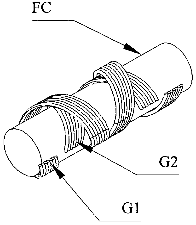
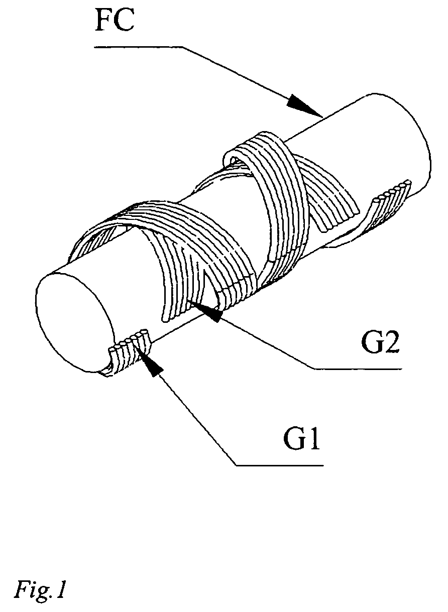
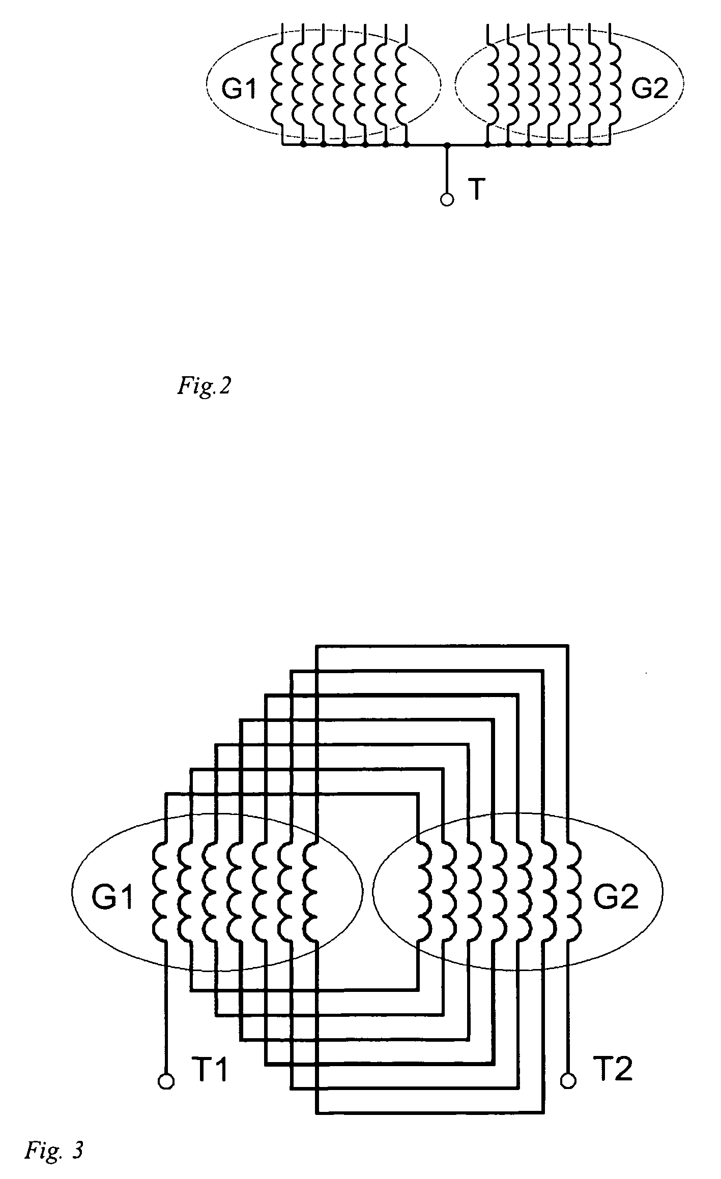
[0030]Electrical shielding of a sensing cable includes a plurality of individually isolated shielding wires. In one embodiment, the shielding wires are arranged into groups wound in mutually opposite directions. In another embodiment, all shielding wires are electrically interconnected in parallel. In a further embodiment, each shielding wire has only one connection point. In yet another embodiment, symmetrical arrangement of shielding consisting of plurality of wires yields high flexibility of sensing cable and minimizes the shielding effective impedance and thus increases the shielding performance. The single connection point of each shielding wire eliminates any flow of induced currents which would affect accuracy.
[0031]A sensing coil includes a plurality of individually isolated sensing wires. In one embodiment, the sensing wires are arranged into groups wound in mutually opposite directions. In another embodiment, the sensing wires, respective to voltages induced in sensing wires by magnetic field of sensed current, are electrically interconnected in series or in parallel or in combination of series and parallel or some sensing wires are idle. The interconnection configuration of sensing wires is used to determine the sensing coil sensitivity, impedance and frequency range. In a further embodiment, symmetrical arrangement of sensing wires eliminates influence of outside current sources.
[0032]In one embodiment, the shielding wires wound in opposite direction can be advantageously mutually twisted. The shielding wire twisting improves the mechanical stability of the winding and increases effective coverage. The shielding wire twisting also improves the electrical symmetry of wire groups thus lowering shielding impedance yielding further increasing of shielding performance.
[0033]In one embodiment, the sensing wires wound in opposite direction can be advantageously mutually twisted. The sensing wire twisting improves the mechanical stability of the winding and thus increases the electrical stability as well. Essential effect of sensing wire twisting is the improvement of symmetry of sensing coil in reference to shielding. The symmetry enables elimination of all common mode residual signals induced by unwanted couplings of the sensing coil to strange sources
[0034]In another embodiment, the flexible current sensor cable can be advantageously manufactured as continuous cable product on coaxial cable making machine with shielding wires and sensing wires arranged according to the invention. The final sensor is then assembled from portion of desired length cut from already manufactured continuous cable. Continuous cable production assures high homogeneity of windings along the cable length thus increasing the sensor's accuracy and manufacturing repeatability. Further advantage is the lower manufacturing cost compared to individual sensor production.

Problems solved by technology

Known constructions of the flexible current sensors have lower amplitude and phase accuracy compared to ferromagnetic current transformer types.
Due to low level of the output voltage of the sensor coil they are sensitive to disturbance, interference and noise generated in evaluation electronics.
Commercially available flexible current sensors on Rogowski principle are due to insufficient accuracy dedicated mainly for informative measurements.
Disadvantage of this approach is the nonlinearity inherent to any soft magnetic material.
This nonlinearity substantially affects the accuracy of the current transformer.
Another disadvantage of the disclaimed composite soft magnetic material core are inherent non-magnetic gaps between magnetic particles lowering the effective permeability and thus leading to low winding inductances and mutual coupling resulting to significant phase and amplitude errors.
The presented combined integrator shows higher frequency band compare to classic simple integrator but at the expense of lower overall accuracy.
Disadvantage of using single coil as electrostatic shielding is its high impedance resulting to weak shielding effect for strange AC field.

Method used


Image

  • Precision flexible current sensor
  • Precision flexible current sensor
  • Precision flexible current sensor

Examples


Embodiment Construction

[0047]At the outset, it should be appreciated that like drawing numbers on different drawing views identify identical, or functionally similar, structural elements of the invention. While the present invention is described with respect to what is presently considered to be the preferred aspects, it is to be understood that the invention as claimed is not limited to the disclosed aspects.

[0048]Furthermore, it is understood that this invention is not limited to the particular methodology, materials and modifications described and as such may, of course, vary. It is also understood that the terminology used herein is for the purpose of describing particular aspects only, and is not intended to limit the scope of the present invention, which is limited only by the appended claims.

[0049]Unless defined otherwise, all technical and scientific terms used herein have the same meaning as commonly understood to one of ordinary skill in the art to which this invention belongs. Although any meth...


PUM


Abstract

A flexible current sensor including a sensing cable with a sensing coil wound on a cylindrical flexible core and electrical shielding located over said sensing coil and an outer isolation coat. The electrical shielding includes a plurality of individually isolated shielding wires arranged into groups wound in mutually opposite directions and / or the sensing coil includes a plurality of individually isolated sensing wires arranged into groups wound in mutually opposite directions.

Description

CROSS-REFERENCE TO RELATED APPLICATIONS[0001]This application is filed under 35 U.S.C. §120 and §365(c) as a continuation-in-part of PCT International Application No. PCT / SK2005 / 000023 filed on Nov. 28, 2005, which application was published in English and which application is incorporated herein by reference.FIELD OF THE INVENTION[0002]The invention is related to sensor circuit for electrical alternating current. More particularly, the invention is directed to improvement of mechanical construction, electrical configuration, electronic evaluation circuit and use of flexible current sensor.BACKGROUND OF THE INVENTION[0003]Flexible current sensors are based on flexible inductive coil which can be formed to create a closed path around the measured current carrying conductor. The voltage induced into the coil is proportional to the derivation of the total current flowing through the enclosed area. This principle of current measurement is well known as the Rogowski principle or the Rogow...

Claims


Application Information

Patent Timeline
Patent Type & Authority Applications(United States)
IPC IPC(8): G01R15/18
CPCG01R15/181
Inventor GRNO, LADISLAV
Owner GRNO LADISLAV
Learn More