Polarizing device, method for manufacturing the same, liquid crystal device, and projection display device

a technology of polarizing device and liquid crystal, which is applied in the direction of polarizing elements, color television details, instruments, etc., can solve the problems of grid pattern with a difficulty in controlling the structure of a pattern in dry etching, and inability to solve the difficulties, etc., to achieve high aspect ratio structure, prevent grid pattern overecthing, and high aspect ratio structure

a technology of polarizing device and liquid crystal, which is applied in the direction of polarizing elements, color television details, instruments, etc., can solve the problems of grid pattern with a difficulty in controlling the structure of a pattern in dry etching, and inability to solve the difficulties, etc., to achieve high aspect ratio structure, prevent grid pattern overecthing, and high aspect ratio structure

US20080303987A1Active Publication Date: 2008-12-11SEIKO EPSON CORP

Image

  • Polarizing device, method for manufacturing the same, liquid crystal device, and projection display device
  • Polarizing device, method for manufacturing the same, liquid crystal device, and projection display device
  • Polarizing device, method for manufacturing the same, liquid crystal device, and projection display device

Examples


first embodiment

[0039]A first embodiment of a polarizing device and a manufacturing method thereof according to the aspects of the invention will now be described with references to drawings. The following figures used in the descriptions below have different scale sizes modified for each of the components, so that each of them will be sufficiently large to be recognized.

Polarizing Device

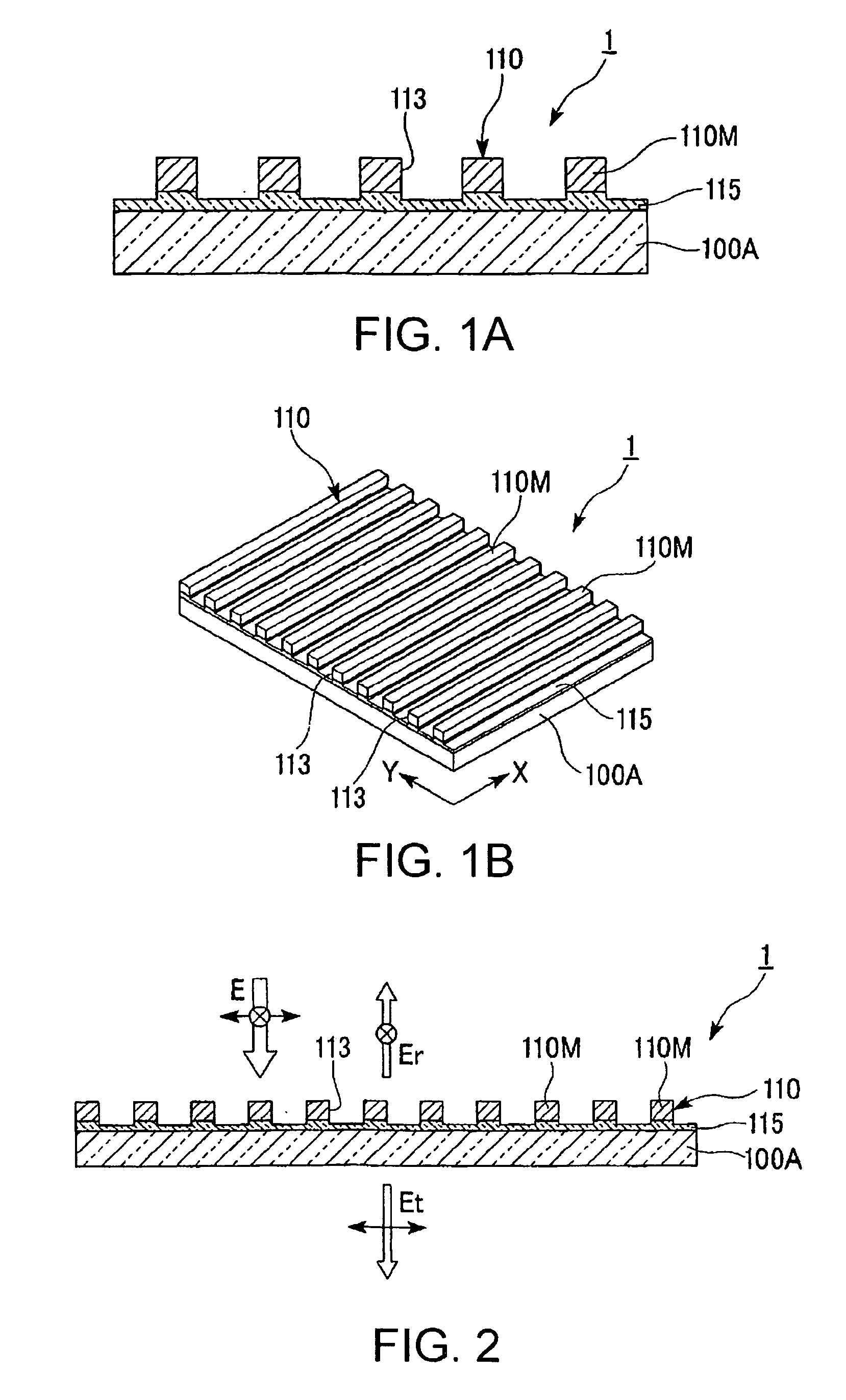
[0040]FIG. 1A is a partial sectional view showing a polarizing device 1 according to this embodiment. FIG. 1B is a perspective view showing polarizing device units 110 constituting the polarizing device. FIG. 2 is an illustration that describes the operation of the polarizing device 1.

[0041]The polarizing device 1 includes an undercoat layer (an etching sacrifice layer) 115 covering a base 100A, and the polarizing device units 110 formed on this undercoat layer 115. The polarizing device units 110 that have a wire grid structure are composed mainly with a metallic film formed including a plurality of openings 113 s...


PUM

PropertyMeasurementUnit
thicknessaaaaaaaaaa
thicknessaaaaaaaaaa
wavelengthaaaaaaaaaa

Abstract

A polarizing device includes: a polarizing device unit composed of a metallic film formed on a base, the metallic film having a plurality of slit-shaped openings; and an etching sacrifice layer provided between the base and the polarizing device unit, so that the etching sacrifice layer is partly etched together with the metallic film during the etching of the polarizing device unit; wherein the etching sacrifice layer is composed of a material that has an etching rate equal to or greater than that of the metallic film.

Description

BACKGROUND[0001]1. Technical Field[0002]The present invention relates to a polarizing device, a method for manufacturing thereof, as well as a liquid crystal device and a projection display device.[0003]2. Related Art[0004]Polarizing devices formed including grid patterns that are shaped on a glass substrate have been suggested as polarizing devices used for light valves in liquid crystal projectors. A line-to-spacing (L / S) ratio, where a grid width is defined as L and a space between grids is defined as S, is an important parameter to determine the optical property of the polarizing devices. For instance, a high optical property is obtained by making the L / S ratio small, in other words, increasing the space between the grids and narrowing the width of the lines.[0005]The aforementioned grid patterns are formed by patterning, for instance, Al with dry etching. The optical property of the polarizing devices is therefore affected by a state of Al during dry etching. However, controlli...

Claims


Application Information

Patent Timeline
11 Dec 2008
Publication
US20080303987A1
IPC
G02B5/30; G02B1/08; G02F1/1335
CPC
G02B5/1857; G02B5/3058; G02F1/133528; G02F2001/133548; H04N9/3167; H04N9/3197; G02F1/133548
Inventors
KUMAI, YOSHITOMO