Image detection method for diagnostic plates

Inactive Publication Date: 2008-12-11
KAIWOOD TECH
View PDF6 Cites 5 Cited by
  • Summary
  • Abstract
  • Description
  • Claims
  • Application Information

AI Technical Summary

Benefits of technology

[0009]Another objective of the present invention is to provide an image detection method for diagnostic plates, which depends on reading the Radio frequency identification (RFID) tags of the diagnostic plates, or the alternative RFID tags provided with an RFID reader, or external files of computers. The corresponding detection parameters are set to save the analytic time and to prevent the data entry error made by human input.
[0010]Yet another objective of the present invention is to provide an image detection method for diagnostic plates, which locates the signal line in the diagnostic plates automatically, and shows consistency in judging negative / positive thresholds to further increase the detection accuracy and analytic efficiency of the automatic system.
[0012]The advantages of the method in the invention are locating the precise sites of the assay regions automatically, locating the signal lines in the diagnostic plates automatically, showing consistency in judging negative / positive thresholds, saving the analytic time and preventing the data entry error made by artificial input, further to increase the detection accuracy and analytic efficiency of the automatic system.

Problems solved by technology

The operator has to be very careful on the sites for detection since signal lines are not at the same level with each other due to manufacturing and assembly error.
The errors occur easily especially when the signal line with single color is faint and vague.
It will be even troublesome if the operator is facing the same color system with large samples and multiple detection items.
The naked eye detection is time-consuming, labor-intensive and not accurate.
The results might be mixed up when many items are tested at the same time, and caused wrong records for the tests.

Method used


Image

  • Image detection method for diagnostic plates
  • Image detection method for diagnostic plates
  • Image detection method for diagnostic plates

Examples


Embodiment Construction

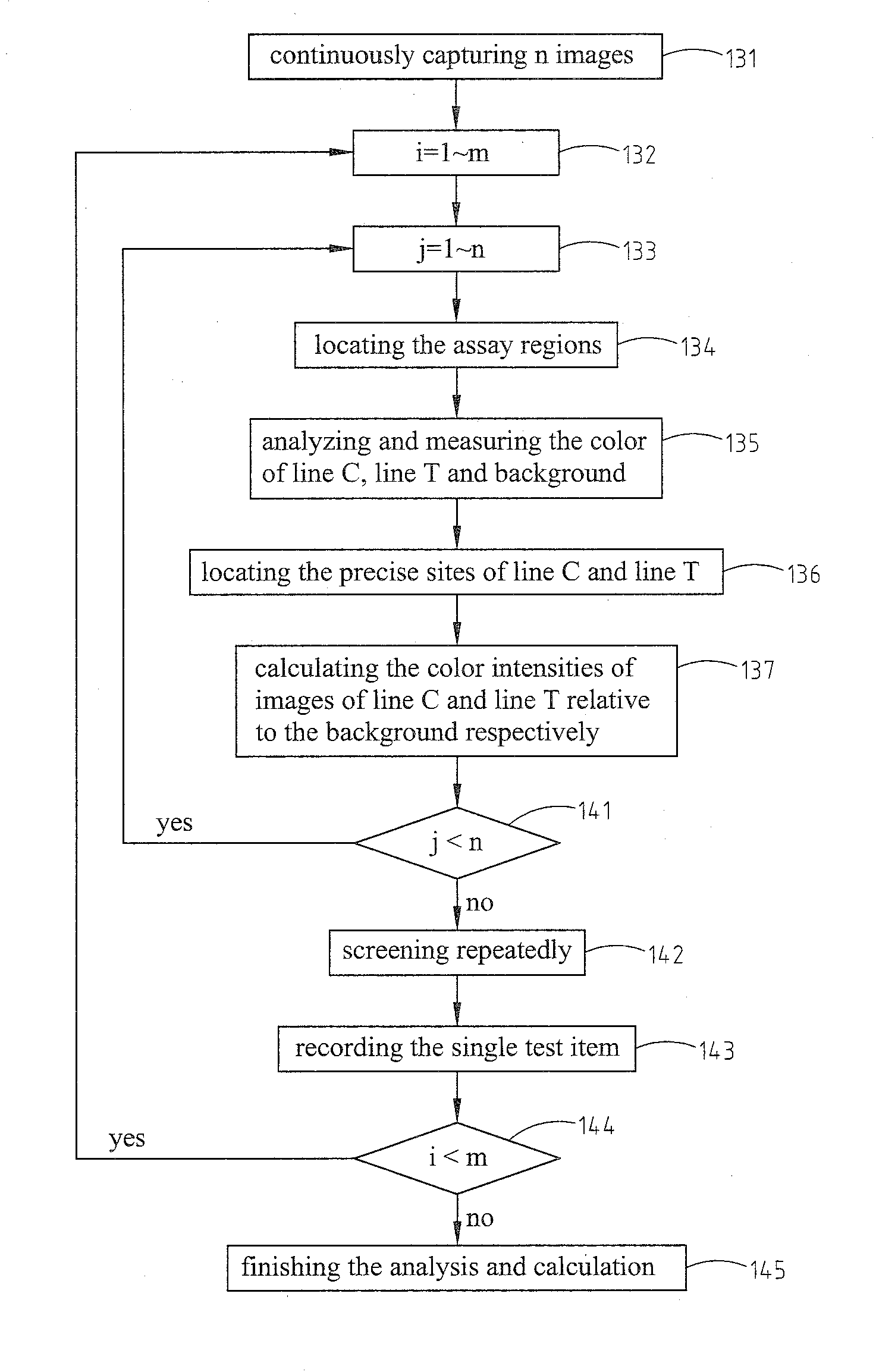
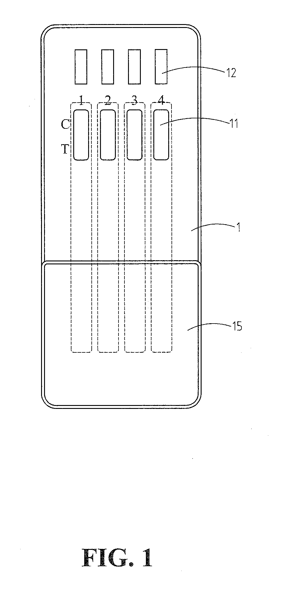
[0020]Referring to FIG. 1, a flow chart shows the preferred embodiment of image detection method for diagnostic plates in the present invention. In this preferred embodiment, the body of the diagnostic plate (1) comprises 4 assay regions (11), in correspondence to 4 test items (12) respectively, two signal lines (C and T) set in the assay regions (11) in the strips (represented by dot lines), and RFID tags (in the back of the diagnostic plate, not shown in the figure, not necessary to be attached to the diagnostic plate). The pattern of the diagnostic plate is shown by way of example but not limitation. The test items (12) include, but are not limited to, the physiological changes / disease screening, such as pregnancy, renal diseases; or medicines / drugs screening, such as benzodiazepines (BZD), marijuana, amphetamine, opium and the like. The operator takes out the lid (15) of the diagnostic plate (1), places the four test strips into the samples such as urine sample, let them immerse...


PUM


Abstract

The present invention relates to an image detection method for diagnostic plates, which detects the changes of signal lines in multiple assay regions at the same time, and promotes the detection efficiency remarkably. The diagnostic plates in the present invention may comprise Radio frequency identification (RFID) tags, and comprise at least one assay region, and at least one signal line within the assay region. This image detection method for diagnostic plates according to the present invention comprises: reading the parameters from the RFID tags of the diagnostic plates directly, or reading the alternative RFID tags provided with an RFID reader, or downloading the parameters from external files of computer; detecting the changes of the images whether reaches the stable state; analyzing and measuring the color of signal lines and the background in the image of the diagnostic plates after the images are stabilized; calculating the color intensity difference between the images of the signal line and the corresponding background; and determining the result of the signal lines in the assay region based on the difference in intensity.

Description

BACKGROUND OF THE INVENTION[0001]1. Field of the Invention[0002]The present invention relates to an image detection method, in particular to an image detection method for diagnostic plates, which detects the changes of signal lines in multiple assay regions at the same time, and promotes the detection efficiency remarkably.[0003]2. The Prior Arts[0004]Biochemical examination has become one of the routine clinical tests. The generally known chromatography diagnosis belongs to the biochemical tests, which is an immunoassay makes the use of the binding between antigens and antibodies, and the result is read by naked eyes. Medical physicians evaluated the physiological condition or the drug addict condition of the patients according to these results. The present method for liquid chromatography depends on the presence of a signal line in single color. The operator has to be very careful on the sites for detection since signal lines are not at the same level with each other due to manufa...

Claims


Application Information

Patent Timeline
IPC IPC(8): G06K9/00
CPCG01N21/8483
Inventor WU, TZU-CHIANGLIN, CHIEN-DER
Owner KAIWOOD TECH
Why Eureka
Try Eureka