

Energy storage device, image forming apparatus including energy storage device, and discharge control method
a technology of energy storage and image forming apparatus, which is applied in the direction of electric variable regulation, instruments, manufacturing tools, etc., can solve the problems of excessive power consumed by the image forming apparatus, consuming excessive power that is not directly necessary for image formation, and requiring a relatively long time of around a few minutes, etc., to achieve a large amount of power in a short period of time, high internal resistance, and low internal resistance
- Summary
- Abstract
- Description
- Claims
- Application Information
AI Technical Summary
Benefits of technology
Problems solved by technology
Method used
Image

Examples
first embodiment
[0063](Hardware Configuration of Image Forming Apparatus)
[0064]In the following, a hardware configuration of an image forming apparatus, such as a printer or a multifunction machine, representing an exemplary apparatus that receives power supplied from an energy storage device according to an embodiment of the present invention is described.
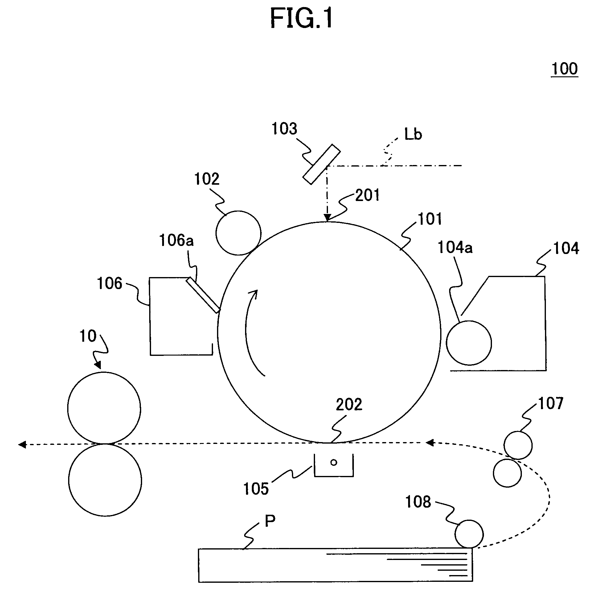
[0065]FIG. 1 is a diagram showing a hardware configuration of an image forming apparatus 100 including a fixing device according to an embodiment of the present invention.
[0066]As is shown in FIG. 1, the image forming apparatus 100 according to the present embodiment includes a drum-shaped photoconductor 101 corresponding to an image carrier that rotates in the direction indicated by arrow 1; a charge device 102 including a charge roller that charges the peripheral face of the photoconductor, a mirror 103 that guides a laser beam (exposure light) Lb to scan the peripheral face of the charged photoconductor 101, which laser beam is irradiated from...
second embodiment
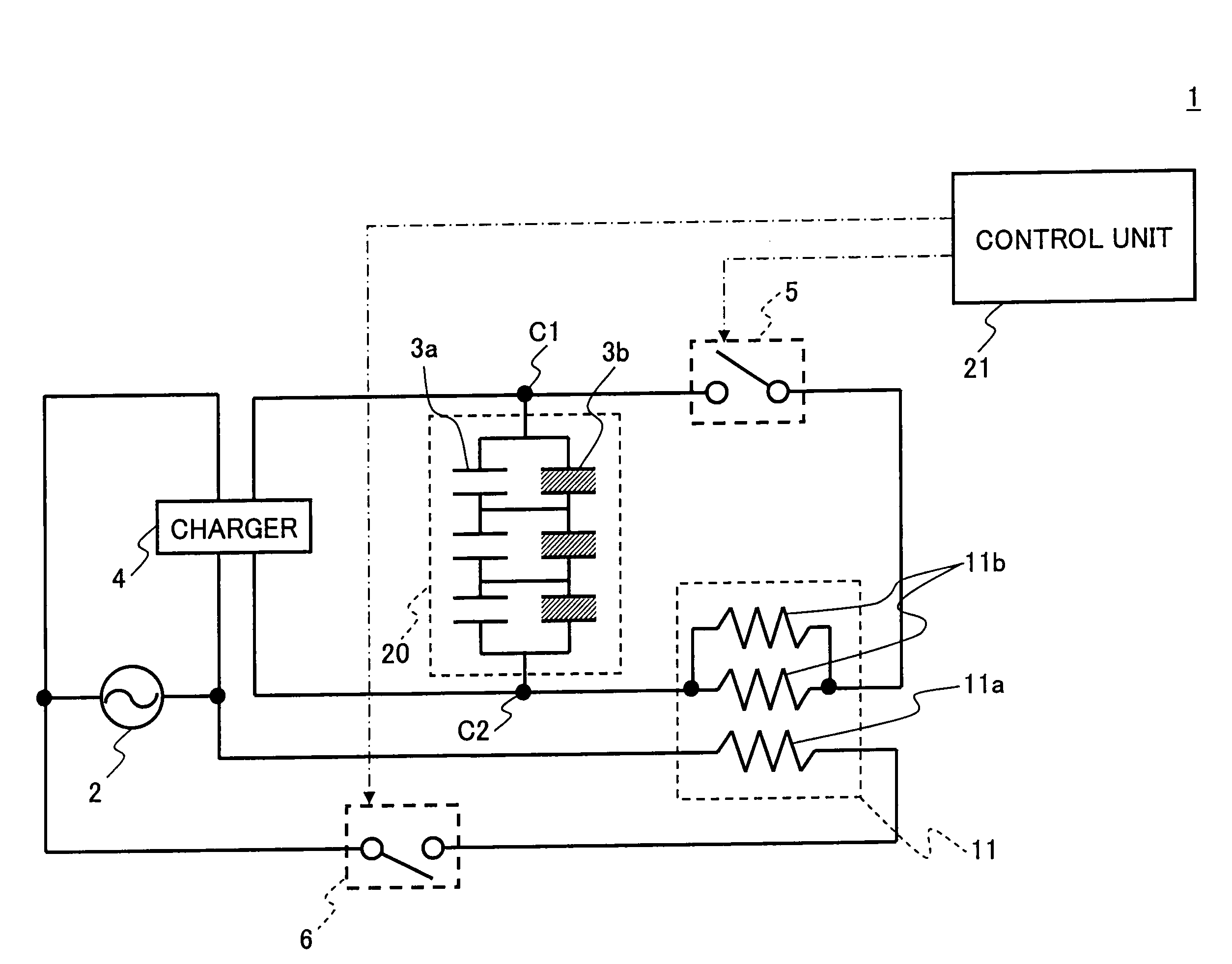
[0177]According to a second embodiment of the present invention, discharge / charge operations of an energy storage device for supplying power to a fixing device of an image forming apparatus are controlled based on information indicating the charge status of the energy storage device as well as information indicating the operation status of the image forming apparatus.
[0178]In other words, the second embodiment differs from the above-described first embodiment in that it uses information indicating the charge status of the energy storage device in controlling discharge / charge operations of an energy storage device that includes different types of capacitor cells having different internal resistance values and is configured to be capable of supplying a large amount of power in a short period of as well as supplying power over a long period of time without being increased in size.
[0179]It is noted that in the following descriptions, elements of the second embodiment that are identical ...
PUM
| Property | Measurement | Unit |
|---|---|---|
| Electrical resistance | aaaaa | aaaaa |
| Electric potential / voltage | aaaaa | aaaaa |
Abstract
Description
Claims
Application Information