Skin material, skin material production method and composite skin for automotive interior trim
a skin material and automotive interior technology, applied in the direction of transportation and packaging, coatings, other domestic articles, etc., can solve the problems that the skin material cannot achieve uniform thickness and good touch, and achieve uniform thickness, improved touch, and improved appearance.
- Summary
- Abstract
- Description
- Claims
- Application Information
AI Technical Summary
Benefits of technology
Problems solved by technology
Method used
Image
Examples
example 1
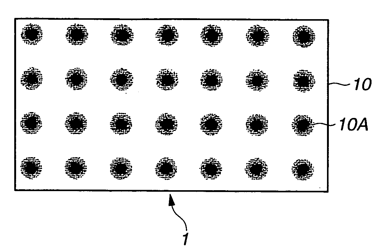
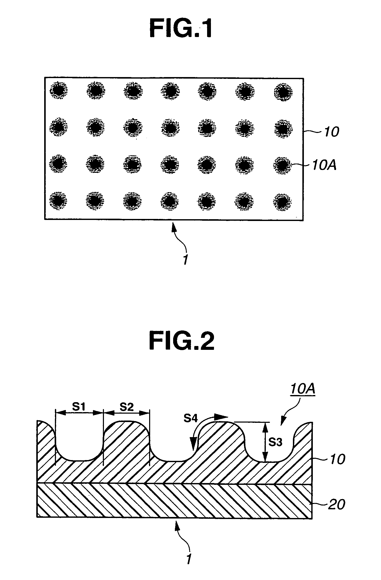
[0065]A two-plate injection mold unit was first prepared as follows. A polyvinyl chloride (PVC) leather of 300×400 mm in size was produced using an original copy of multiple embossed pattern where fine round-edged recesses were superimposed on ordinary embossed pattern. Herein, the fine recesses had a projected area ratio of 20%, a depth of 100 μm, a pitch of 50 to 300 μm, a maximum diameter of 100 μm and a round edge curvature radius of 100 μm. A reverse model of the PVC leather produced prepared. A molding plate (as a front mold) was then electroformed according to the reverse model of the PVC leather. Another molding plate (as a back mold) was formed so as to define a mold cavity of specific thickness by combination with the electroformed molding plate.
[0066]A silicon-based (silicon-based wax-containing) release agent “ACMOS” was applied to the front and back molds uniformly at 15 g / m2 by means of a spray gun “IWATA W-100” under the condition that the front and back molds were he...
example 2
[0073]A two-plate injection mold unit was prepared as follows. A PVC leather of 300×400 mm in size was produced using an original copy of multiple embossed pattern where fine round-edged recesses were superimposed on ordinary embossed pattern. Herein, the fine recesses had a projected area ratio of 20%, a depth of 100 μm, a pitch of 100 μm, a maximum diameter of 100 μm and a round edge curvature radius of 100 μm. A reverse model of the PVC leather was produced. A molding plate (as a front mold) was then electroformed according to the reverse model of the PVC leather. Another molding plate (as a back mold) was formed to define a mold cavity of specific thickness by combination with the electroformed molding plate.
[0074]A skin material was produced in the same manner as in Example 1, except for using the above-prepared mold unit. In the resulting skin material, the polymeric layer was formed on the substrate as an in-mold coating with an embossed pattern of fine round-edged recesses a...
example 3
[0075]A two-plate injection mold unit was prepared as follows. A PVC leather of 300×400 mm in size was produced using an original copy of multiple embossed pattern where fine round-edged recesses were superimposed on ordinary embossed pattern. Herein, the fine recesses had a projected area ratio of 20%, a depth of 50 μm, a pitch of 100 μm, a maximum diameter of 100 μm and a round edge curvature radius of 100 μm. A reverse model of the PVC leather was produced. A molding plate (as a front mold) was then electroformed according to the reverse model of the PVC leather. Another molding plate (as a back mold) was formed to define a mold cavity of specific thickness by combination with the electroformed molding plate.
[0076]A skin material was produced in the same manner as in Example 1, except for using the above-prepared mold unit. In the resulting skin material, the polymeric layer was formed on the substrate as an in-mold coating with an embossed pattern of fine round-edged recesses an...
PUM
| Property | Measurement | Unit |
|---|---|---|
| Fraction | aaaaa | aaaaa |
| Length | aaaaa | aaaaa |
| Density | aaaaa | aaaaa |
Abstract
Description
Claims
Application Information
 - R&D
- Intellectual Property
- Life Sciences
- Materials
- Tech Scout
- Unparalleled Data Quality
- Higher Quality Content
- 60% Fewer Hallucinations
Browse by: Latest US Patents, China's latest patents, Technical Efficacy Thesaurus, Application Domain, Technology Topic, Popular Technical Reports.
© 2025 PatSnap. All rights reserved.Legal|Privacy policy|Modern Slavery Act Transparency Statement|Sitemap|About US| Contact US: help@patsnap.com


