
Treating method for brittle member

Active Publication Date: 2008-12-11
LINTEC CORP
View PDF6 Cites 55 Cited by
  • Summary
  • Abstract
  • Description
  • Claims
  • Application Information

AI Technical Summary

Benefits of technology

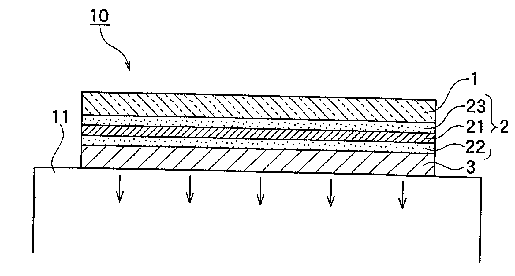
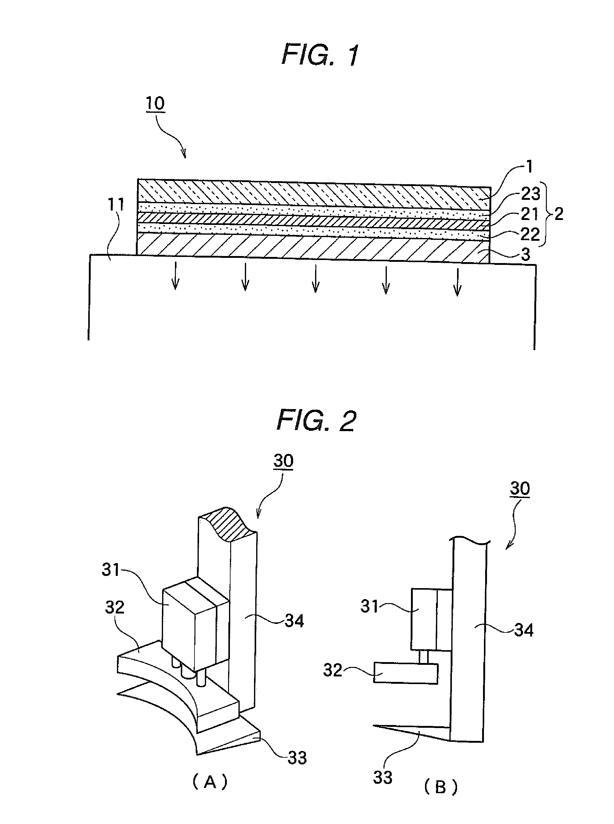
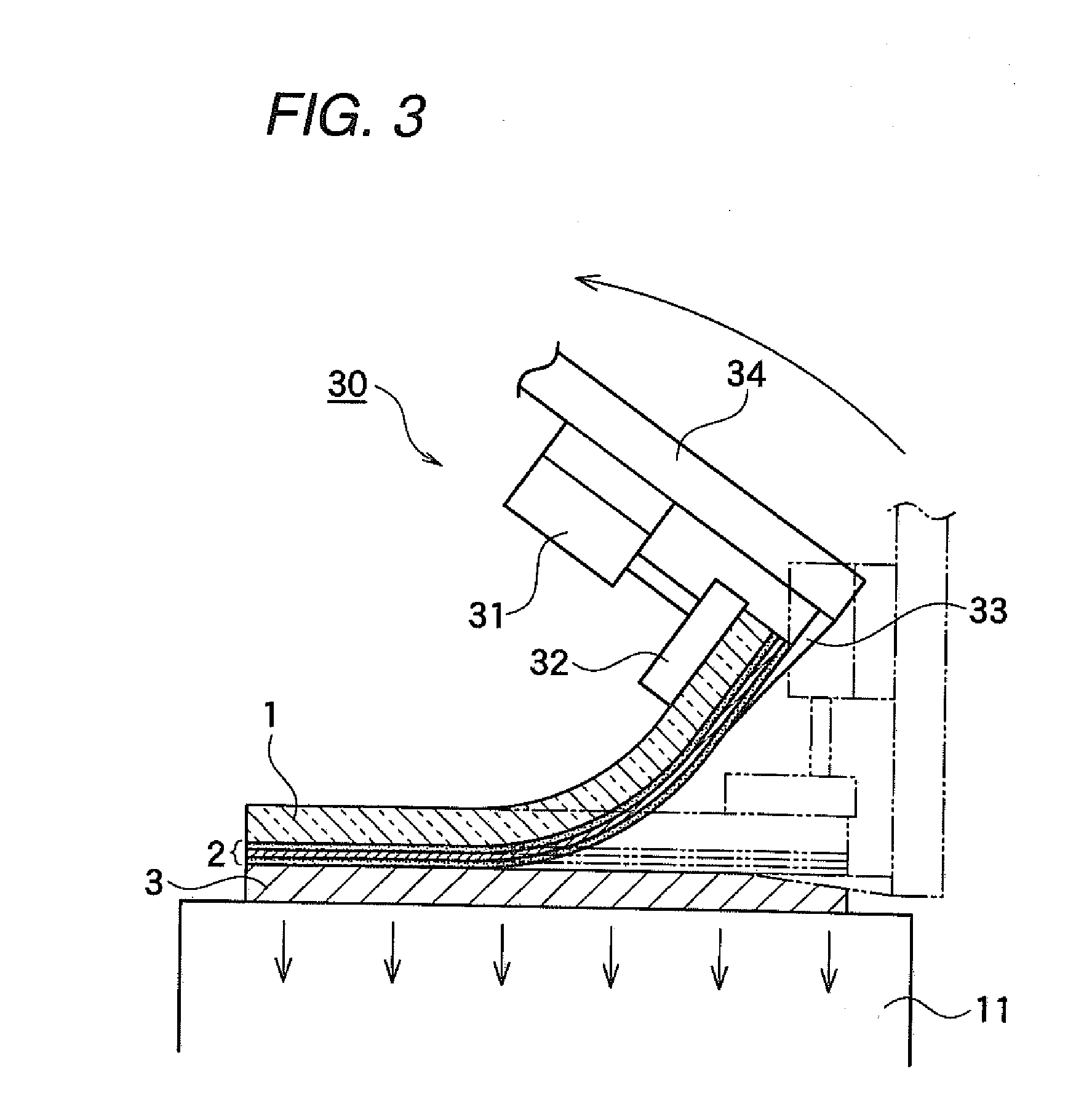
[0033]In the present invention, because of protecting a brittle member fixed on a flexible glass plate, the brittle member can be held without deformation when transporting, storing, processing the brittle member, a high thickness accuracy treatment of the brittle member can be applied. Also, as it is different from a conventionally used rigid glass plate, breakage of the brittle member can be prevented without deformation of the brittle member when separating the flexible glass base plate from the brittle member, since a flexible glass base plate can be curved or bent.

Problems solved by technology

As the wafer which is a brittle member becomes thinner, possibilities of breakage becomes higher when processing or transporting.
However, according to a method for laminating the wafer and the hard plate by the double-sided adhesive sheet, wafer is broken at sometimes, when separating both members after finishing a series of process.
However, since it is impossible or very hard to bend the hard plate, the wafer side has to be curved inevitably.
Therefore, the wafer is broken since strain is loaded to the wafer which is brittle.

Method used


Image

  • Treating method for brittle member
  • Treating method for brittle member
  • Treating method for brittle member

Examples


example 1

(Manufacturing Double-Sided Adhesive Tape)

[0083]As adhesive agents A and B, following adhesive agents are prepared.

[0084]Adhesive agent A: adhesive agent composed by mixing 100 parts by weight of copolymer having weight average molecular weight 400,000 obtained by copolymerizing 85 parts by weight of 2-ethylhexylacrylate and 15 parts by weight of 2-hydroxyethylacrylate and cross linking agent composed of 9.4 parts by weight of adduct of tolylene diisocyanate with trimethylolpropane.

[0085]Adhesive Agent B: adhesive agent composed by mixing 100 parts by weight of copolymer having weight average molecular weight 500,000 obtained by copolymerizing 80 parts by weight of butylacrylate and 10 parts by weight of methylmethacrylate and 5 parts by weight of 2-hydroxyethylacrylate and cross linking agent composed of 0.9 parts by weight of adduct of tolylene diisocyanate with trimethylolpropane.

[0086]To a polyethylene terephthalate (PET) film having thickness of 50 μm, the adhesive agent A was ...

example 2

[0089]A similar operation as in the above example 1 was conducted except for separating the flexible glass base plate by using separating means shown in FIG. 7. The holding and separating properties were good.

example 3

(Manufacturing Flexible Glass Base Plate)

[0090]Material mixture of glass having the same composition ratio as in the example 1 was heated for 5 hours at 1500 to 1600° C. to melt, the molten liquid was casted on a steel plate and pressing, a glass plate was obtained. Next, the glass plate was cut to be desired size and polished, and a circular glass plate having diameter of 201 mm and thickness of 1 mm was obtained. Subsequently, the glass plate was dipped into 360° C. of molten salt mixture of KNO3:60%, NaNO3:40% for three hours to perform ion-exchanging of the glass surface portion, and a chemically reinforced flexible glass base plate B having compression stress layer of 100 μm was obtained. The maximum curving angle of the glass was about 32 degree. A similar operation as in the above example 2 was conducted except for separating the flexible glass base plate B by using separating means shown in FIG. 7. The holding and separating properties were good.


PUM

PropertyMeasurementUnit
Angleaaaaaaaaaa
Diameteraaaaaaaaaa
Flexibilityaaaaaaaaaa

Abstract

An object of the present invention is to provide a treating method for brittle member capable of stably holding the brittle member when applying predetermined treatments such as transportation and grinding back surface of a brittle member such as a semi-conductor wafer and separating the brittle member without breakage after finishing required treatment to thereby attaining high thickness accuracy of the brittle member.A treating method for brittle member comprising: a step of removably fixing a brittle member on a flexible glass base plate, a step of treating said brittle member, a step of fixing said brittle member side by holding means, and a step of separating said flexible glass base plate from said brittle member by bending said flexible glass base plate.

Description

FIELD OF THE INVENTION[0001]The present invention relates to a treating method for a brittle member when applying desired processing such as transportation and grinding back surface of a brittle member such as a semi-conductor wafer.DESCRIPTION OF THE RELATED ART[0002]According to popularization of IC Card in recent years, reducing the thickness of a semi-conductor wafer which is constitutional member for manufacturing IC chip progresses. It being required that a thickness of the wafer which is conventionally 350 μm and the like is to make thinner as 50 to 100 μm or less.[0003]As the wafer which is a brittle member becomes thinner, possibilities of breakage becomes higher when processing or transporting. Therefore, in case that grinding the wafer until ultra thin and transporting the ultra thin wafer, it is preferable to proceed operation thereof with fixing and protecting the wafer on a hard plate such as a glass plate or acrylic plate by a double-sided adhesive sheet and the like....

Claims


Application Information

Patent Timeline
IPC IPC(8): B24B1/00H01L21/304H01L21/683
CPCB24B7/228H01L21/67126H01L21/67132H01L21/67219
Inventor OHASHI, HITOSHIIZUMI, NAOFUMI
Owner LINTEC CORP
Learn More