
Reciprocating Saw Blade Having Variable-Height Teeth and Related Method

a saw blade and variable-height technology, applied in the field of saw blades, can solve the problems of reducing the cutting force of the saw blade, reducing the cutting speed and/or durability, and requiring a trade, so as to improve the cutting speed and/or durability, and improve the cutting force. the effect of performan

Active Publication Date: 2008-12-18
BLACK & DECKER INC
View PDF7 Cites 85 Cited by
  • Summary
  • Abstract
  • Description
  • Claims
  • Application Information

AI Technical Summary

Benefits of technology

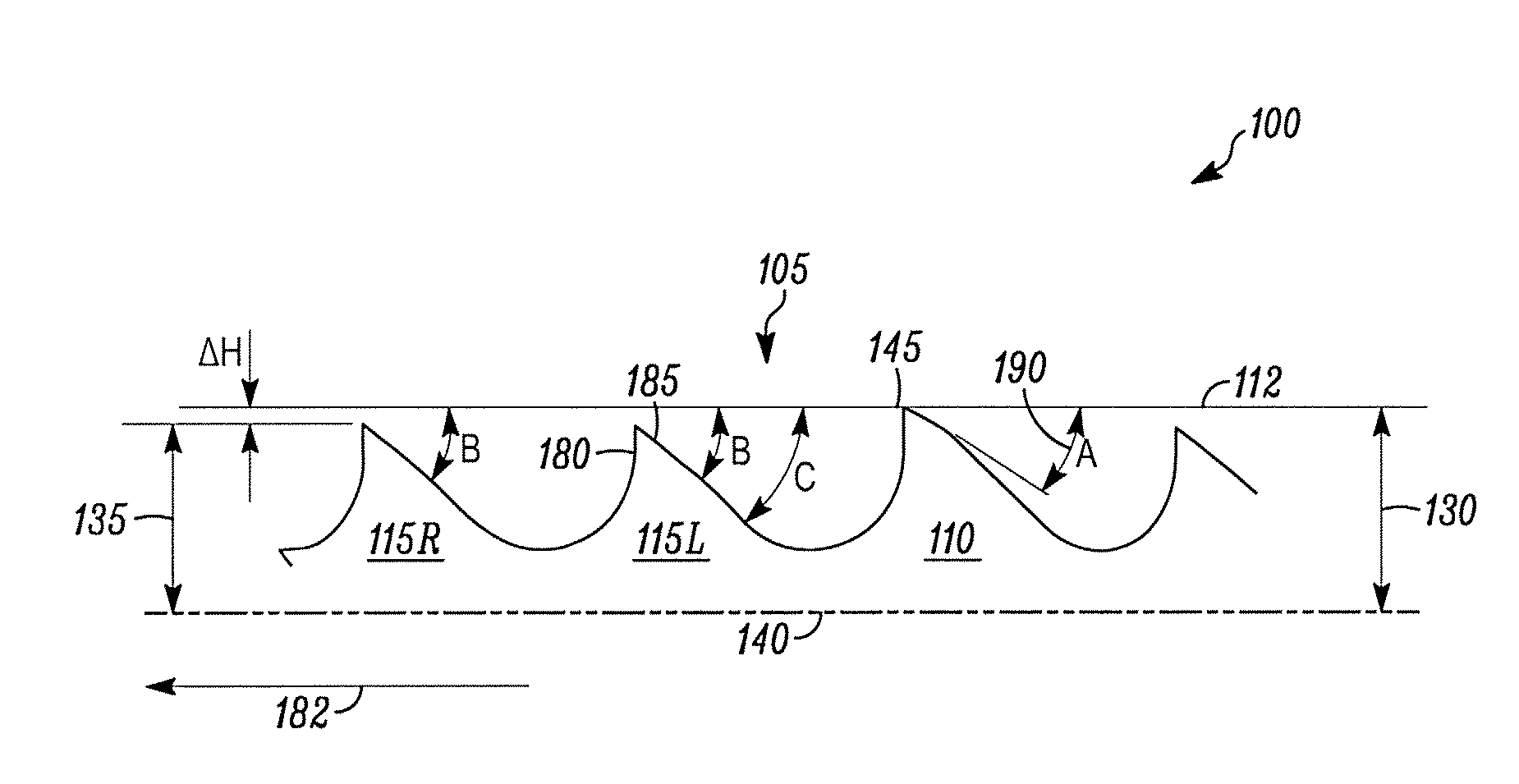
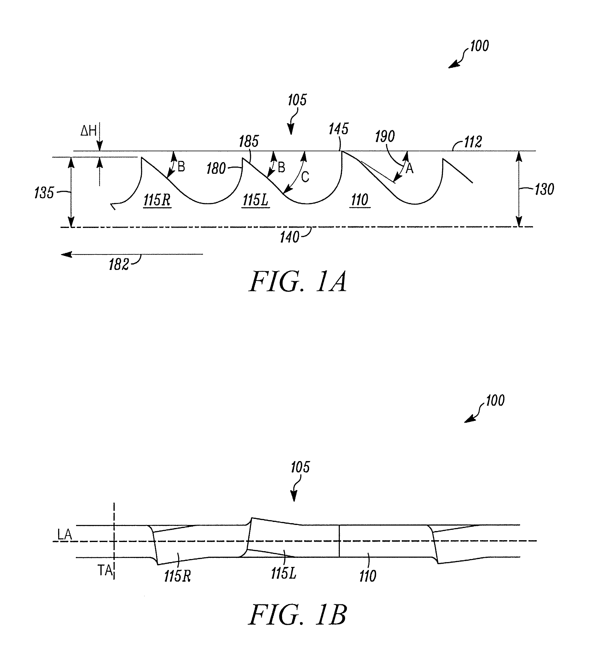
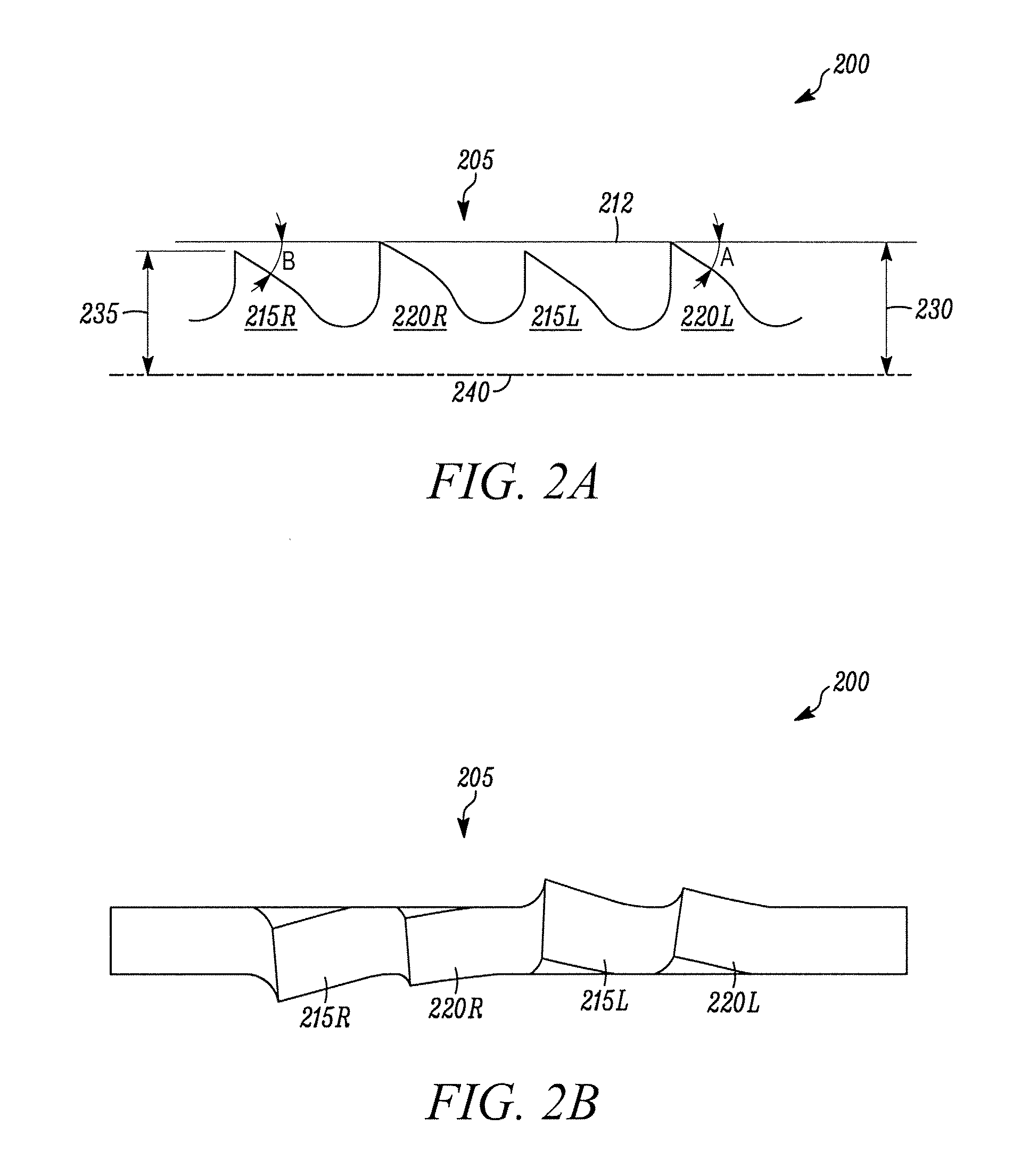
[0021]Cutting the work piece by engaging the work piece with the reciprocatingly driven reciprocating saw blade and, in turn, during each of a plurality of forward strokes, engaging multiple teeth of the same species with the work piece, bearing a relatively higher chip load with the relatively high teeth in comparison to the relatively low teeth, protecting the relatively low teeth from chipping or damage with the preceding relatively high teeth, and cutting the work piece with the relatively low teeth at a higher speed in comparison to the relatively high teeth.
[0023]One advantage of the reciprocating saw blades of the present invention is that the height differential between cutting teeth can provide significantly improved performance, such as improved cutting speed and / or durability, in comparison to prior art recip blades. Accordingly, the reciprocating saw blades of the present invention are capable of withstanding higher cutting forces, providing increased chip production, and improved cutting speeds in comparison to prior art reciprocating saw blades.
[0025]Yet another advantage of some currently preferred embodiments of the present invention is that the acute cutting angle formed between the plane defined by the cutting edge and the plane defined by the reciprocating motion of the saw can further enhance cutting speed without materially impacting the durability of the blade. In some embodiments, this acute angle is at least partially a result of the tang extending at an acute angle relative to the cutting edge (e.g., a line extending between the tips of successive unset teeth or teeth of the same height). The steeper the cutting angle, the greater is the height differential between the high and low teeth, and thus the effect on cutting performance provided by such height differential. Yet another advantage is that the acute cutting angle formed between the cutting edge plane and the plane defined by the reciprocating motion of the saw does not increase the load on the clearance surfaces of the teeth on the return stroke of the blade, thereby further enhancing performance without reducing durability.

Problems solved by technology

Typical reciprocating saw blades suffer from the need for a trade-off between maximizing wear resistance and maximizing durability.
However, teeth with greater clearance angles may be more delicate and thus more likely subject to breakage than teeth with shallower clearance angles.
The need to restrict the clearance angle is especially acute for reciprocating blades, because the reciprocating cutting pattern is very abusive to blade teeth.
Thus, not only are the rake faces subject to substantial cutting forces, but the clearance surfaces formed on the back sides of the teeth likewise are subject to substantial cutting forces on the return strokes.
Recip blades are particularly susceptible to failure from tooth fracture or chipping.
Accordingly, it has been believed that if high-low teeth were applied to a recip blade, the relatively high teeth would be overly exposed and subjected to excessive cutting forces, and thus more likely subject to fracture or chipping.
Similarly, it has been believed that if relatively steep clearance angles were applied to recip teeth (e.g., about 35° or greater) any teeth with such narrow included angles would be too delicate to withstand the relatively abusive reciprocating cutting action and associated cutting forces, and therefore would be subject to premature fracture or chipping.
Accordingly, the performance of prior art recip blades, such as cutting life and / or durability, have not always been at levels desired.

Method used


Image

  • Reciprocating Saw Blade Having Variable-Height Teeth and Related Method
  • Reciprocating Saw Blade Having Variable-Height Teeth and Related Method
  • Reciprocating Saw Blade Having Variable-Height Teeth and Related Method

Examples


Embodiment Construction

[0045]In FIGS. 1A and 1B, a first embodiment of a reciprocating saw blade of the present invention is indicated generally by the reference numeral 100. The saw blade 100 is used in a reciprocating saw. A reciprocating saw is a portable power saw that is typically hand-held and includes a chuck for releasably engaging the saw blade and driving the saw blade in a reciprocating motion. Reciprocating saws are sometimes referred to as recip saws or jig saws and these terms are used synonymously herein. Reciprocating saws are typically driven by an electric motor (cord or cordless), or are pneumatically driven. Reciprocating saws are driven in any of a variety of cutting actions, including orbital, linear and / or angled. Reciprocating saw blades are blades that include at least one tang for mounting the blade within the chuck of a reciprocating saw. Reciprocating saw blades are sometimes referred to as recip blades or jig saw blades and these terms are used synonymously herein.

[0046]The re...


PUM

PropertyMeasurementUnit
heightaaaaaaaaaa
clearance angleaaaaaaaaaa

Abstract

A reciprocating saw blade, for use in a portable power reciprocating saw including a chuck for releasably engaging the saw blade, includes a tang having an elongated axis and being engageable with the chuck for attaching the saw blade to the reciprocating saw. The saw further includes a blade portion having a cutting edge that defines a plurality of cutting teeth. The cutting teeth define a repeating pattern of successive groups of teeth. Each group of teeth is less than about a half inch in length, and includes a plurality of laterally offset teeth, at least one relatively high first tooth and at least one relatively low second tooth. Prior to tooth set, the at least one relatively high first tooth is at least about 0.002 inch higher than the at least one relatively low second tooth.

Description

CROSS-REFERENCE TO PRIORITY APPLICATION[0001]This patent application claims priority on U.S. Provisional Patent Application Ser. No. 60 / 934,262 filed Jun. 12, 2007, entitled “Reciprocating Saw Blade Having Variable-Height Teeth And Related Method”, which is hereby incorporated by reference in its entirety as part of the present disclosure.FIELD OF THE INVENTION[0002]The present invention relates to saw blades, and more particularly, to reciprocating saw blades including recurring patterns of high and low teeth and related methods.BACKGROUND[0003]A reciprocating saw machine is a hand-held power saw that includes a chuck for releasably engaging the saw blade and driving the saw blade in a reciprocating motion through a work piece. The reciprocating motion can be an orbital cutting action, a straight or linear cutting action, or an angled cutting action. Reciprocating saws are sometimes referred to as recip saws, or jig saws, and reciprocating saw blades likewise are sometimes referred...

Claims


Application Information

Patent Timeline
Patent Type & Authority Applications(United States)
IPC IPC(8): B23D61/12B26D1/06
CPCB23D61/121Y10T83/9355Y10T83/04Y10T83/935Y10T83/9319Y10T83/9454Y10T83/9346B27B33/02B27B33/04B27B33/00
Inventor ELLISTON, ASIFKORB, WILLIAM B.HAMPTON, STEPHEN A.
Owner BLACK & DECKER INC
Learn More