Brightness with reduced optical losses

a technology of optical loss reduction and illumination, applied in the field of illumination systems, can solve the problems of insufficient illumination, limited magnification, and inability to achieve high brightness of leds, and achieve the effect of optimizing the spectrum of illumination and high brightness of illuminating ligh

Inactive Publication Date: 2008-12-18
MICROALIGN TECH
View PDF2 Cites 76 Cited by
  • Summary
  • Abstract
  • Description
  • Claims
  • Application Information

AI Technical Summary

Benefits of technology

[0016]One object of the invention is to provide a compact illumination system for illuminating an object with white light obtained by mixing the light of various colors and delivering that light to a light-mixing unit from individual color light sources through optical-fiber light guides. Another object is to provide the aforementioned illumination system with an optimized spectrum of illumination. Even a further object is to provide a compact illumination system of the aforementioned type that is characterized by high brightness of the illuminating light. It is another object of the present invention to find the most optical balance between the contradicting geometrical and optical parameters of the aforementioned components from the viewpoint of minimization of luminous energy losses.

Problems solved by technology

In laparoscopy and microsurgery, optical-computed tomography, as well as in conventional and confocal optical microscopy, illumination of the object of interest is an extremely important issue.
In microscopy, for example, magnification is limited not by resolution capacity of the optical system but rather by the lack of sufficient illumination.
Many attempts have been made to achieve this objective, and some of these attempts were successful for application in certain fields, but LEDs are still inferior to high-pressure short-arc xenon lamps in achieving high brightness.
However, the above-described illumination system does not teach any means for mixing the spatial light spectrum.
Loss of brightness as a result of mixing light beams of different colors is the main disadvantage of the system of US Patent Application No 20060237636.
In principle, the proposed method allows the brightness of illumination to be increased in comparison with the brightness of a separate Illumination source (laser diode) used in the disclosed setup, but the complexity of the optical scheme and expensive components (dichroic mirrors) will limit the capacity of the system if laser diodes rather than LEDs are used.
Nevertheless, this illumination system has limited brightness and is intended for general illumination of large areas where brightness is not an issue.
Unfortunately, beam-combining elements and setup of the aforementioned illumination cannot increase brightness by combining the light beams emitted from light-emitting diodes because the optical system of the aforementioned device is characterized by high losses of luminous energy.
This is a further proof of the fact that the use of a solid-state illumination system that allows control of spectral characteristics of illumination is a very important issue.
However, as mentioned above, the problem of increasing brightness provided by such system remains unsolved.

Method used


Image

  • Brightness with reduced optical losses
  • Brightness with reduced optical losses
  • Brightness with reduced optical losses

Examples


Embodiment Construction

[0029]For better understanding the principle of the present invention and terminology used in the description, it will be advantageous first to consider some theoretical aspects of the illumination system of the invention.

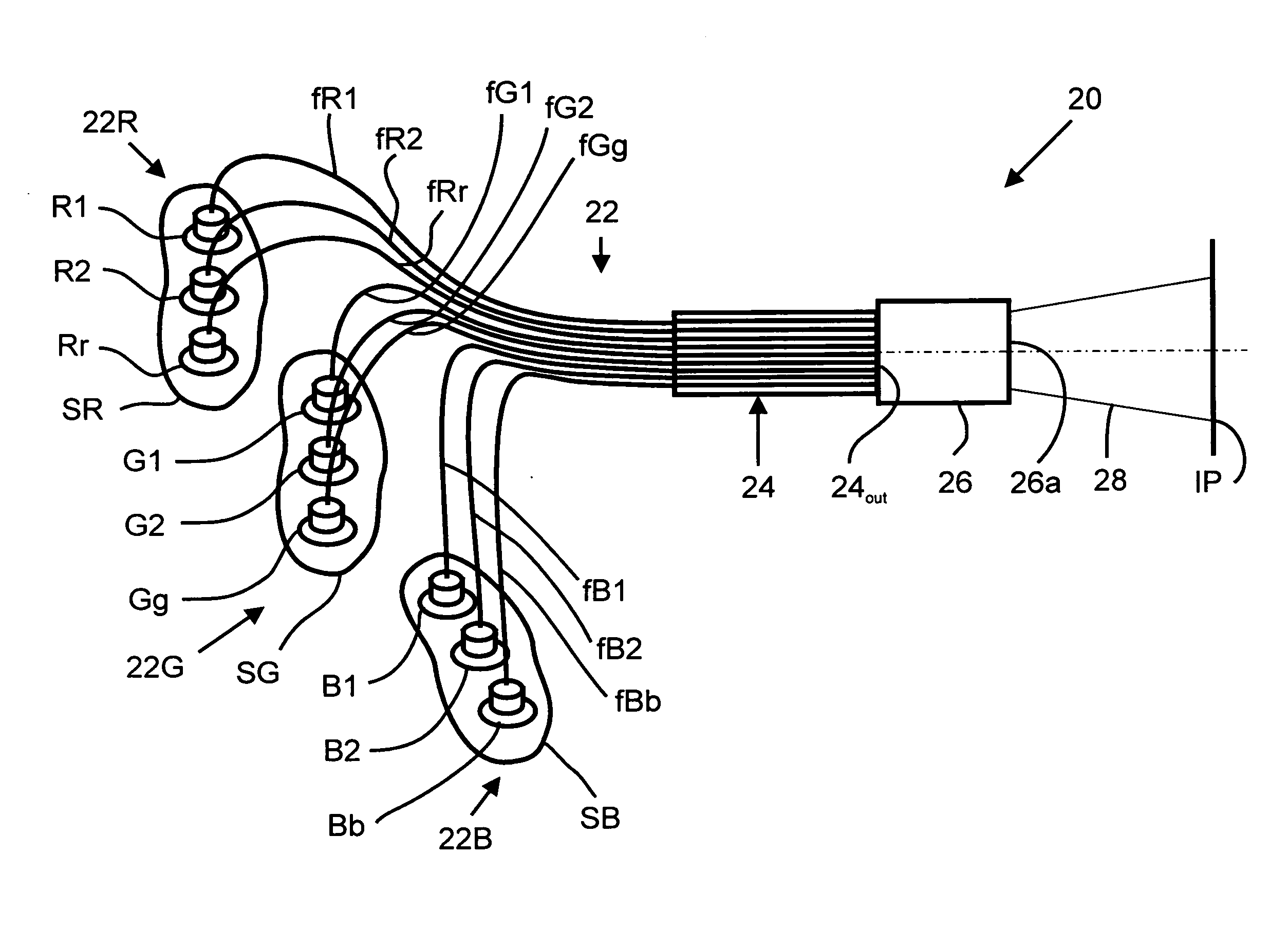
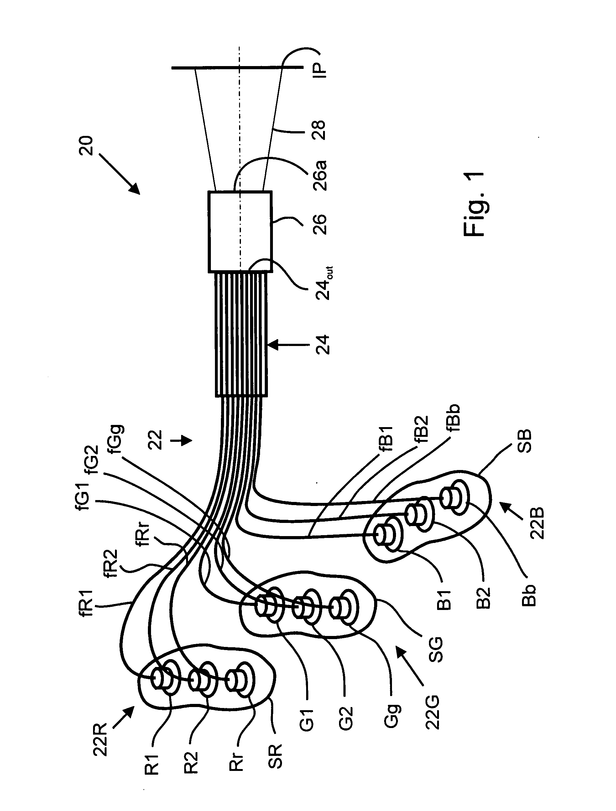
[0030]Let us assume that the illumination system of the invention consists of “n” LEDs, “n” individual light guides with “n” respective light-collecting units for projecting light from the LEDs to the light guides, which are then packed into a bundle that forms a common light guide. Let us further assume that the exit end face of the common compacted light guide is perpendicular to the direction of propagation of light and has a diameter “D”. For simplicity of the consideration, let us first consider the case when the individual light guides are single-fiber light guides. In this case we will assume that all the LEDs are identical, i.e., have identical spectra, their emitters are squares with a side “a”, and their surface brightness is “Bi”.

[0031]With reference to ...


PUM


Abstract

A fiber-bundle illumination system of high brightness with reduced optical losses comprises a plurality of light sources that emit lights of different colors and transmit the component lights of different colors to a light mixer through individual optical-fiber light guides assembled into a bundle, which is crimped at least at the inlet and outlet ends. Unique features of the system are optical coupling between the light sources and their respective light guides and mixing colors in a predetermined proportion that results in spatially uniform distribution of the spectrum on the illuminated area. The system may be used in conjunction with optical instruments such as endoscopic cameras, microscopes, etc.

Description

FIELD OF THE INVENTION[0001]The present invention relates to illumination systems and, more particularly, to an illumination system having a light-transmitting unit in the form of an optical-fiber bundle that delivers light from a light source to the system outlet.BACKGROUND OF THE INVENTION[0002]In laparoscopy and microsurgery, optical-computed tomography, as well as in conventional and confocal optical microscopy, illumination of the object of interest is an extremely important issue. In microscopy, for example, magnification is limited not by resolution capacity of the optical system but rather by the lack of sufficient illumination. The factor of achievable illumination, in turn, depends on the brightness of a light-emitting source, and, therefore, attempts of finding ways to increase the brightness of light sources have continued for many decades.[0003]It is known that lamps such as high-pressure short-arc xenon illuminators, which are characterized by extremely high brightness...

Claims


Application Information

Patent Timeline
Patent Type & Authority Applications(United States)
IPC IPC(8): G02B6/04
CPCG02B6/0006G02B6/0008G02B6/4249A61B1/07
Inventor GUREVICH, IGORFAYBISHENKO, VICTORPASHININ, ANATOLYVELIKOV, LEONIDZUBOV, BORIS
Owner MICROALIGN TECH
Why Eureka
Try Eureka