Eureka AIR delivers breakthrough ideas for toughest innovation challenges, trusted by R&D personnel around the world.

Fuel processor having temperature control function for co shift reactor and method of operating the fuel processor

a technology of co-shift reactor and temperature control function, which is applied in the direction of electrochemical generators, sustainable manufacturing/processing, carburetor gases, etc., can solve the problem of rapid reduction of the performance of the fuel cell, the temperature of the co-shift reactor b>15/b>/i>cannot be easily controlled

Inactive Publication Date: 2008-12-18
SAMSUNG SDI CO LTD
View PDF3 Cites 7 Cited by
  • Summary
  • Abstract
  • Description
  • Claims
  • Application Information

AI Technical Summary

Benefits of technology

The present invention provides a fuel processor with an active temperature control function for a CO shift reactor and a method of operating the fuel processor. The fuel processor comprises a reformer, a burner, a CO shift reactor, a heating element, and a cooling element. The cooling element can cool the CO shift reactor through heat exchange with cooling water or cooling gas, and the heating element can heat the CO shift reactor through heat exchange with a heating gas. The method of operating the fuel processor involves supplying the heat exchange flow line with cooling gas when the temperature inside the CO shift reactor is below a predetermined temperature, supplying the heat exchange flow line with cooling water when the temperature inside the CO shift reactor is above a predetermined temperature, and supplying the heat exchange flow line with heating gas when the temperature inside the CO shift reactor is above a predetermined temperature. The fuel cell system comprises a fuel cell stack and the fuel processor. The technical effects of the invention include improved control of CO shift reactor temperature, improved fuel conversion efficiency, and improved fuel cell performance.

Problems solved by technology

However, the electricity generated by a unit cell typically does not have a high voltage to be useful.
If a fuel containing 10 ppm or more CO is supplied to the stack 20, electrodes are poisoned, resulting in a rapid reduction of the performance of the fuel cell.
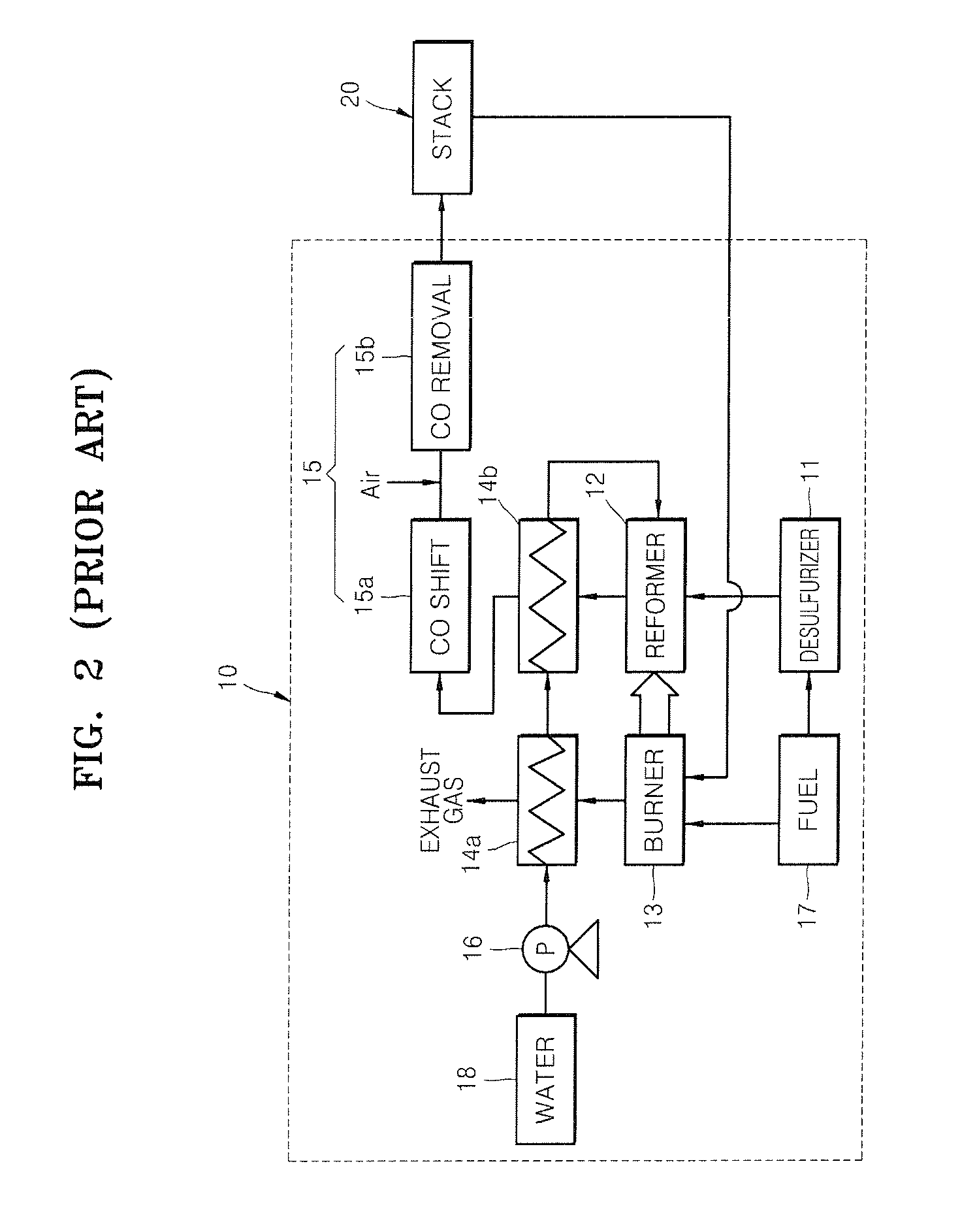
Therefore, the temperature of the CO shift reactor 15a cannot be easily controlled.
However, it is known that, when the temperature of the CO shift reactor 15a exceeds an appropriate level, CO is not sufficiently removed.
If the temperature of the CO shift reactor 15a is not readily controlled, there is a high possibility that the stack 20 may be damaged by CO.
That is, CO cannot be properly removed.
However, the fuel processor 10 does not have a cooling function.
Therefore, in case of a heavy load, the fuel processor 10 cannot operate stably.

Method used


Image

  • Fuel processor having temperature control function for co shift reactor and method of operating the fuel processor
  • Fuel processor having temperature control function for co shift reactor and method of operating the fuel processor
  • Fuel processor having temperature control function for co shift reactor and method of operating the fuel processor

Examples


Embodiment Construction

[0031]Reference will now be made in detail to the present embodiments of the present invention, examples of which are illustrated in the accompanying drawings, wherein like reference numerals refer to the like elements throughout. The embodiments are described below in order to explain the present invention by referring to the figures.

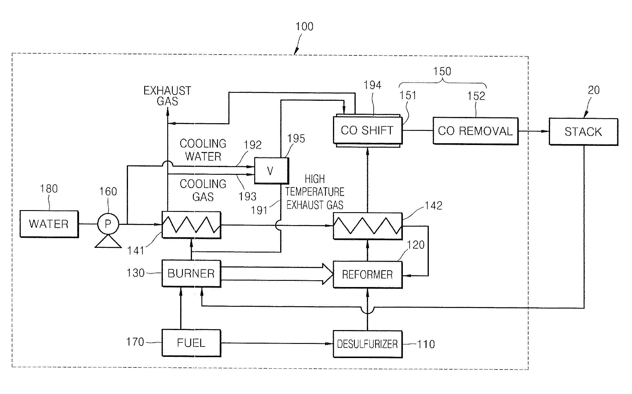
[0032]FIG. 3 is a block diagram of a fuel processor 100 according to an embodiment of the present invention. FIG. 4 is a schematic drawing for explaining a heat exchange process in the CO shift reactor of the fuel processor of FIG. 3. The fuel processor 100 includes a desulfurizer 110, a reformer 120, a burner 130, and a CO removal unit 150 consisting of a CO shift reactor 151 and a CO remover 152. The fuel processor 100 has a basic structure in which, when a raw gas such as a natural gas is supplied from a fuel tank 170, sulfur components included in the raw gas are removed by adsorption in the desulfurizer 110, and hydrogen that is to be supplied to ...


PUM

PropertyMeasurementUnit
temperatureaaaaaaaaaa

Abstract

A fuel processor includes a reformer that generates hydrogen gas by reacting a fuel source and water; a burner that heats the reformer to a temperature suitable for a hydrogen generation reaction; a CO shift reactor that removes CO generated during the hydrogen generation reaction in the reformer; a heating element for heating the CO shift reactor; and a cooling element for cooling the CO shift reactor, wherein the cooling element comprises at least one of a cooling water flow line for heat exchange with the CO shift reactor when cooling water flows through the cooling water flow line and a cooling gas flow line for heat exchange with the CO shift reactor when a cooling gas, which is a burner exhaust gas that has heat exchanged with cooling water, flows through the cooling gas flow line. When the fuel processor is operated, a stable CO removal performance can be maintained since the temperature of the CO shift reactor can be actively controlled.

Description

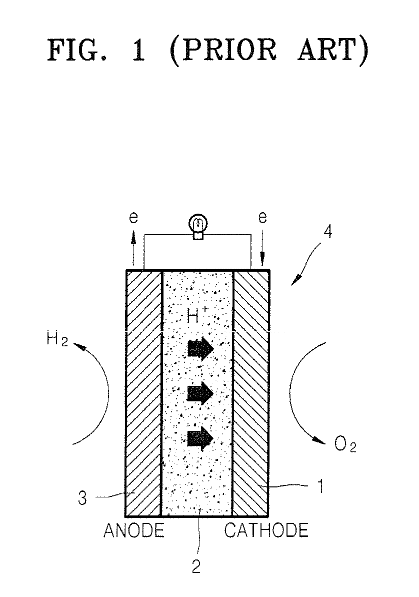
CROSS-REFERENCE TO RELATED APPLICATION[0001]This application claims the benefit of Korean Application No. 2006-111892, filed Nov. 13, 2006, in the Korean Intellectual Property Office, the disclosure of which is incorporated herein by reference.BACKGROUND OF THE INVENTION[0002]1. Field of the Invention[0003]Aspects of the present invention relates to a fuel processor that reforms a fuel suitable for using in a fuel cell system. More particularly, aspects of the present invention relate to a fuel processor having a temperature control function for a CO shift reactor, and a method of operating the fuel processor.[0004]2. Description of the Related Art[0005]A fuel cell is an electricity generator that changes the chemical energy of a fuel into electrical energy through a chemical reaction. The fuel cell can continuously generate electricity as long as the fuel is supplied. FIG. 1 is a schematic drawing illustrating the energy transformation structure of a conventional fuel cell. Referri...

Claims


Application Information

Patent Timeline
Patent Type & Authority Applications(United States)
IPC IPC(8): H01M8/18C10J1/20
CPCC01B3/34C01B3/48C01B2203/0216C01B2203/0233C01B2203/0283C01B2203/0435C01B2203/047C01B2203/066C01B2203/0811C01B2203/0822C01B2203/0827C01B2203/0894C01B2203/1258H01M8/04007H01M8/0612H01M8/0668Y02E60/50Y02P20/10H01M8/06H01M8/04
Inventor LEE, KANG-HEEKIM, SOON-HOLEE, DOO-HWANLEE, HYUN-CHUL
Owner SAMSUNG SDI CO LTD
Why Eureka
Eureka Blog
Learn More