

Apparatus and Method for Reducing Interference
- Summary
- Abstract
- Description
- Claims
- Application Information
AI Technical Summary
Benefits of technology
Problems solved by technology
Method used
Image

Examples
Embodiment Construction
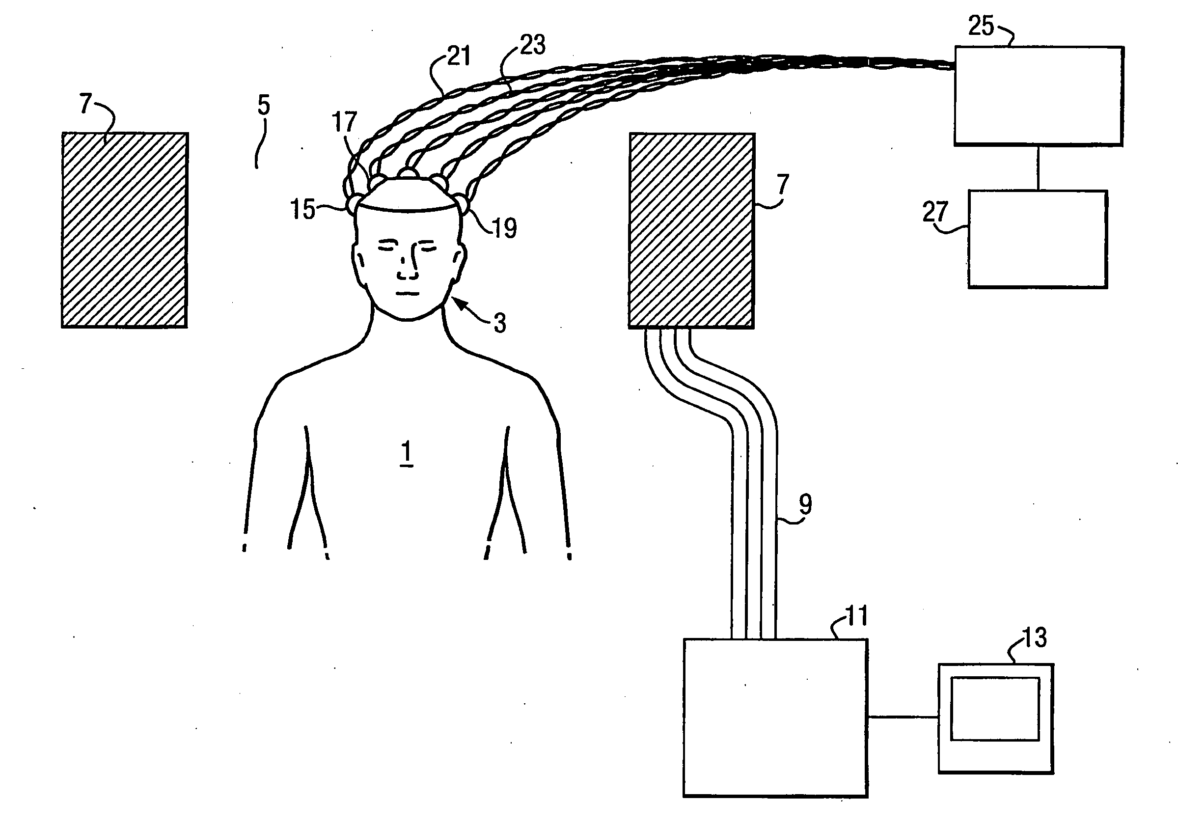
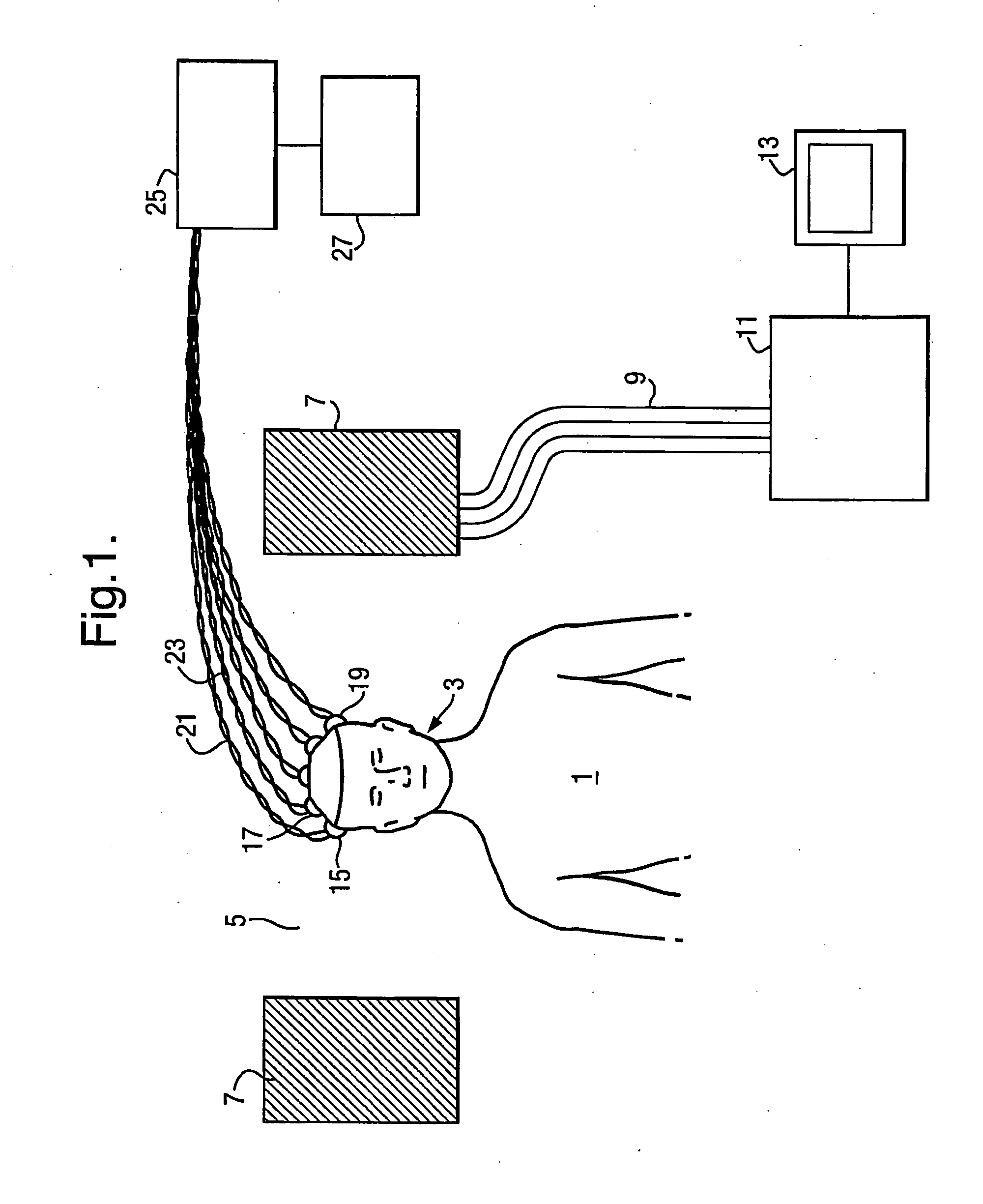
[0134]FIG. 1 shows a basic fMRI and EEG system in which the apparatus and method of one or more embodiments of the present invention may be employed.
[0135]As shown in FIG. 1, a subject 1 is arranged with the subject's head 3 located within the bore 5 of an fMRI coil unit 7 which carries magnetic field windings and rf coils. These coils and windings are energised via a multiplicity of wiring connections 9 etc which connect the coil unit 7 to operational circuitry 11. The operational circuitry unit is connected to a memory and display unit 13 whereby the MRI scans can be stored, displayed and printed at will.
[0136]A plurality of electrodes 15, 17, 19 etc for obtaining EEG signals are attached to the scalp of the subject 1. As will be explained in more detail hereinbelow, one of these electrodes 19 is a “reference electrode”. Signals from the electrodes 15, 17, 19 etc are conveyed by wires 21, 23 etc to an EEG control unit 25 which is connected to a recorder 27 situated outside the MRI...
PUM
 Abstract
Description
Claims
Application Information