
Method for Measuring Electric Current in a Plurality of Conductors

a technology of electric current and conductor, which is applied in the direction of magnetic measurement, magnetic field measurement using galvano-magnetic devices, and hardware monitoring, etc., can solve the problems of connection to the conductor, the device based on the electrical shunt is also known, and the device is expensive and bulky. , to achieve the effect of precise determination of the current, no loss, and easy us

Inactive Publication Date: 2008-12-18
VALEO EQUIP ELECTRIC MOTEUR
View PDF11 Cites 33 Cited by
  • Summary
  • Abstract
  • Description
  • Claims
  • Application Information

AI Technical Summary

Benefits of technology

[0013]Thus a technical problem to be resolved by this object of the present invention is to propose a method of measuring the electric current in a plurality of conductors that would be inexpensive, without losses and easy to use, whilst guaranteeing precise determination of the currents sought.
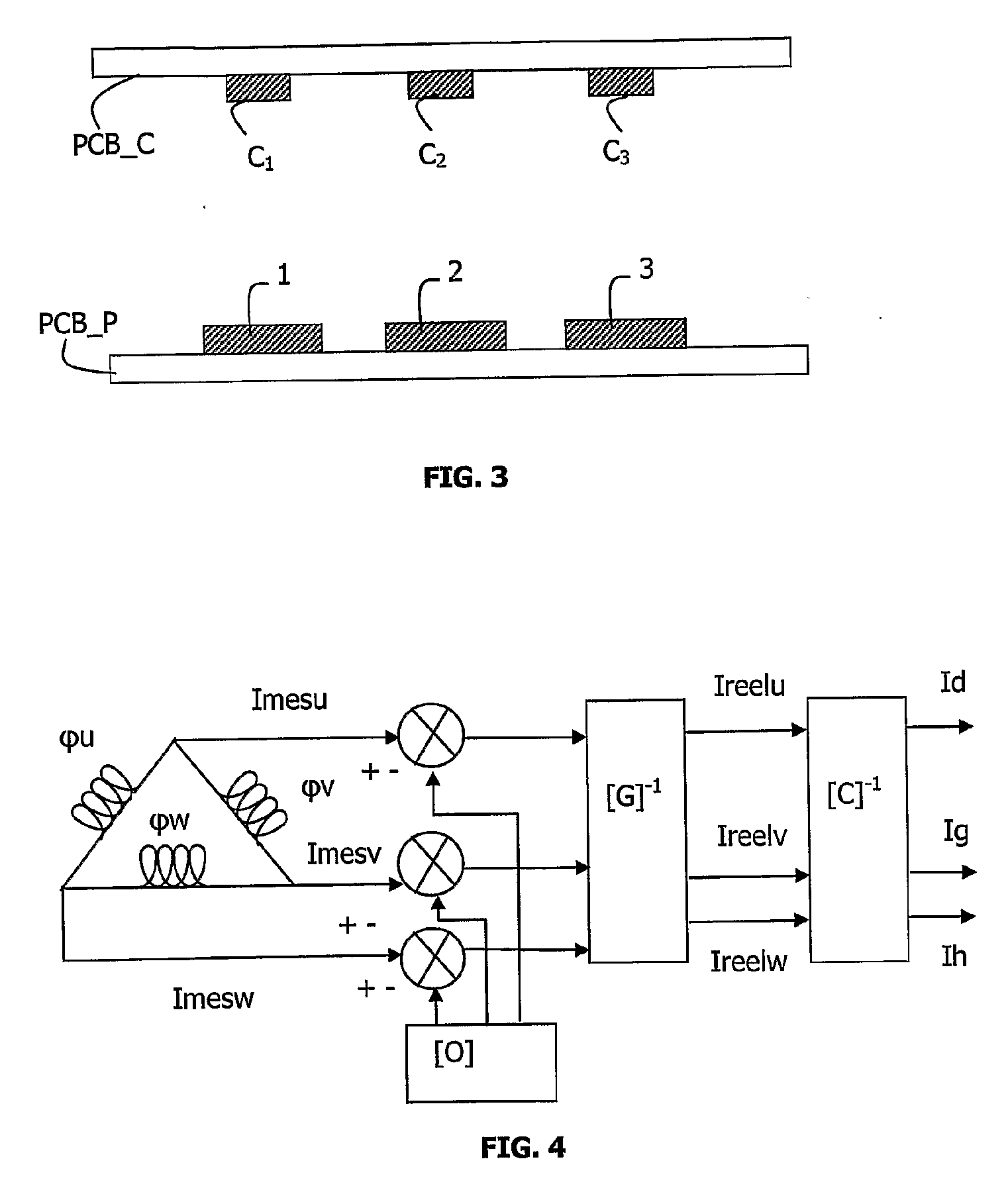
[0023]This last provision has the advantage that the numeric regulation processor includes, by means of a single matrix, both the measurement of the currents (the matrix that is the inverse of the decorrelation matrix) and a transformation making it possible to change from an n-phase reference frame to a two-phase reference frame (inverse projection matrix).

Problems solved by technology

However, these devices are expensive, bulky and complex to use since they require firstly a connecting link between the sensor and the control unit normally referred to as a control card and secondly passing each conductor of bus-bar through a ferrite magnetic circuit.
Devices based on electrical shunts are also known, which are however not well suited if it is wished to measure very intense currents (800 A for example) with few losses by Joule effect.
In addition, there exist problems of connection to the conductors.
Finally, in the case of low shunt values there is a great deal of impreciseness with regard to the measurements of the low currents.

Method used


Image

  • Method for Measuring Electric Current in a Plurality of Conductors
  • Method for Measuring Electric Current in a Plurality of Conductors
  • Method for Measuring Electric Current in a Plurality of Conductors

Examples


Embodiment Construction

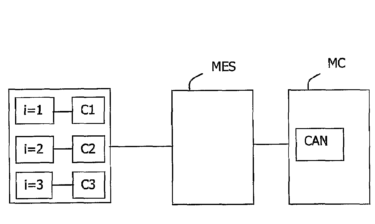
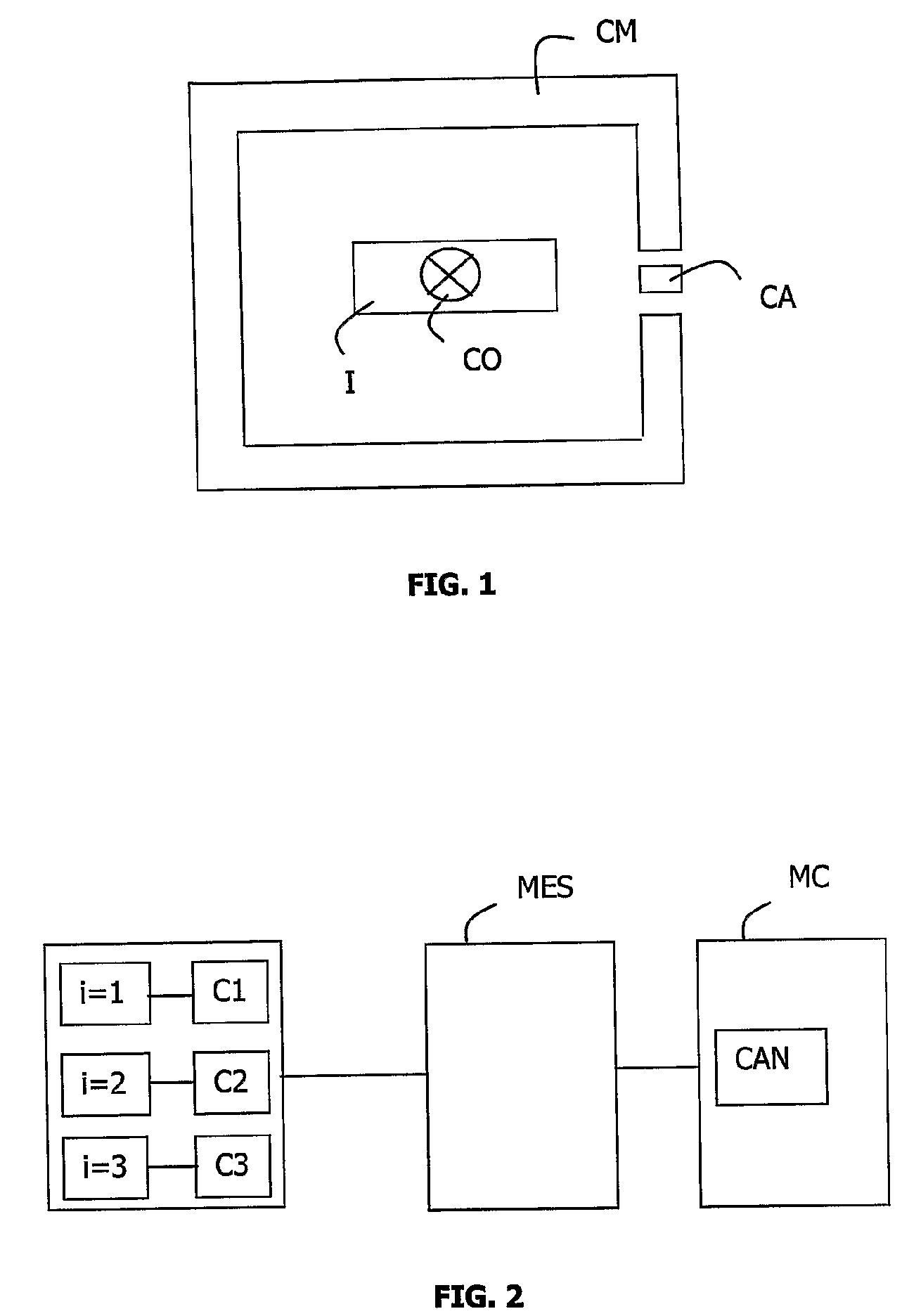
[0030]FIG. 2 depicts a device intended for measuring the electric current in n conductors each marked by the letter i.

[0031]This device comprises:[0032]sensors Ci intended to measure the magnetic field corresponding to each of the n conductors,[0033]a circuit MES for measuring the voltage corresponding to each electric current passing through the conductors i, this circuit being intended to transpose the voltage measured at the terminals of the sensors Ci from a first reference (for example −10V, +10V) into a second reference (for example OV-5V), and[0034]a measurement management microcontroller MC intended in particular to control the stator currents, the said microcontroller comprising an analogue to digital converter CAN intended to convert the transposed measurement (between 0V-5V) issuing from the measurement circuit MES into a digital unit preferentially in 8, 10 or 12 bits, which corresponds to 256, 512 or 1024 points).

[0035]In the case depicted in FIG. 2, the conductors are ...


PUM


Abstract

A method and system for measuring electric current in a plurality (n) of conductors. According to the invention, the method comprises the following steps: an electric current transducer is place substantially opposite to each conductor (I, i=1, . . . , n); a decorrelation matrix ([G]), which is a function of the position of the transducers in relation to the conductors, is constructed; the current (Imesi) in each conductor (i) is measured with the aid of electric current transducers and real currents (Ireeli) are deduced with the aid of the decorrelation matrix ([G]) and the measured currents (Imesi).

Description

FIELD OF THE INVENTION[0001]The present invention concerns a method of measuring an electric current in a plurality of conductors and a device for implementing such a method.[0002]The invention finds a particularly advantageous application in the field of rotary electrical machines used in the automotive industry.PRIOR ART[0003]Motor vehicles with a thermal engine can be equipped with reversible electrical machines, also referred to as alternator / starters, functioning both in alternator mode and in motor mode on starting up or as an aid to boosting as from 500 revolutions / min for the thermal engine.[0004]The reversible electrical machine also comprises a power unit and a control unit, the said power unit serving as a current inverter in starter mode and as current rectifier in alternating mode and is controlled by the control unit.[0005]In this type of machine, it is necessary to be able at all times to control the torque supplied or taken off by the alternator / starter. However, thi...

Claims


Application Information

Patent Timeline
Patent Type & Authority Applications(United States)
IPC IPC(8): G01R19/20G01R19/02
CPCG01R15/202G01R31/007G01R19/15
Inventor CHEMIN, MICHAELLEROUX, FREDERICBERNARD, FRANCOIS-XAVIER
Owner VALEO EQUIP ELECTRIC MOTEUR
Learn More