

Electrically-active ferromagnetic particle conductimetric biosensor test kit
a conductimetric and ferromagnetic particle technology, applied in the field of conductimetric biosensor devices, can solve the problems of reducing affecting the efficiency of assay, and affecting the application of samples to the test devi
- Summary
- Abstract
- Description
- Claims
- Application Information
AI Technical Summary
Problems solved by technology
Method used
Image

Examples
example 1
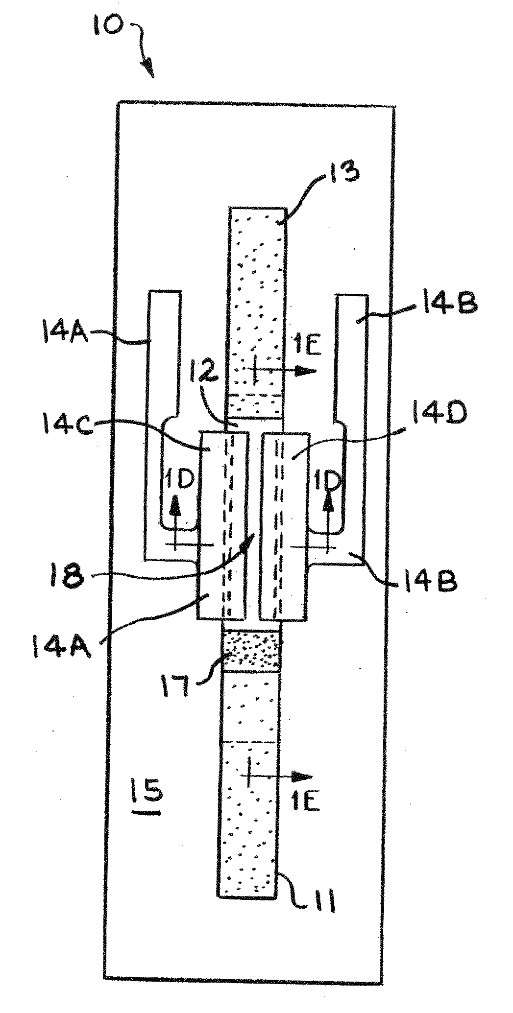
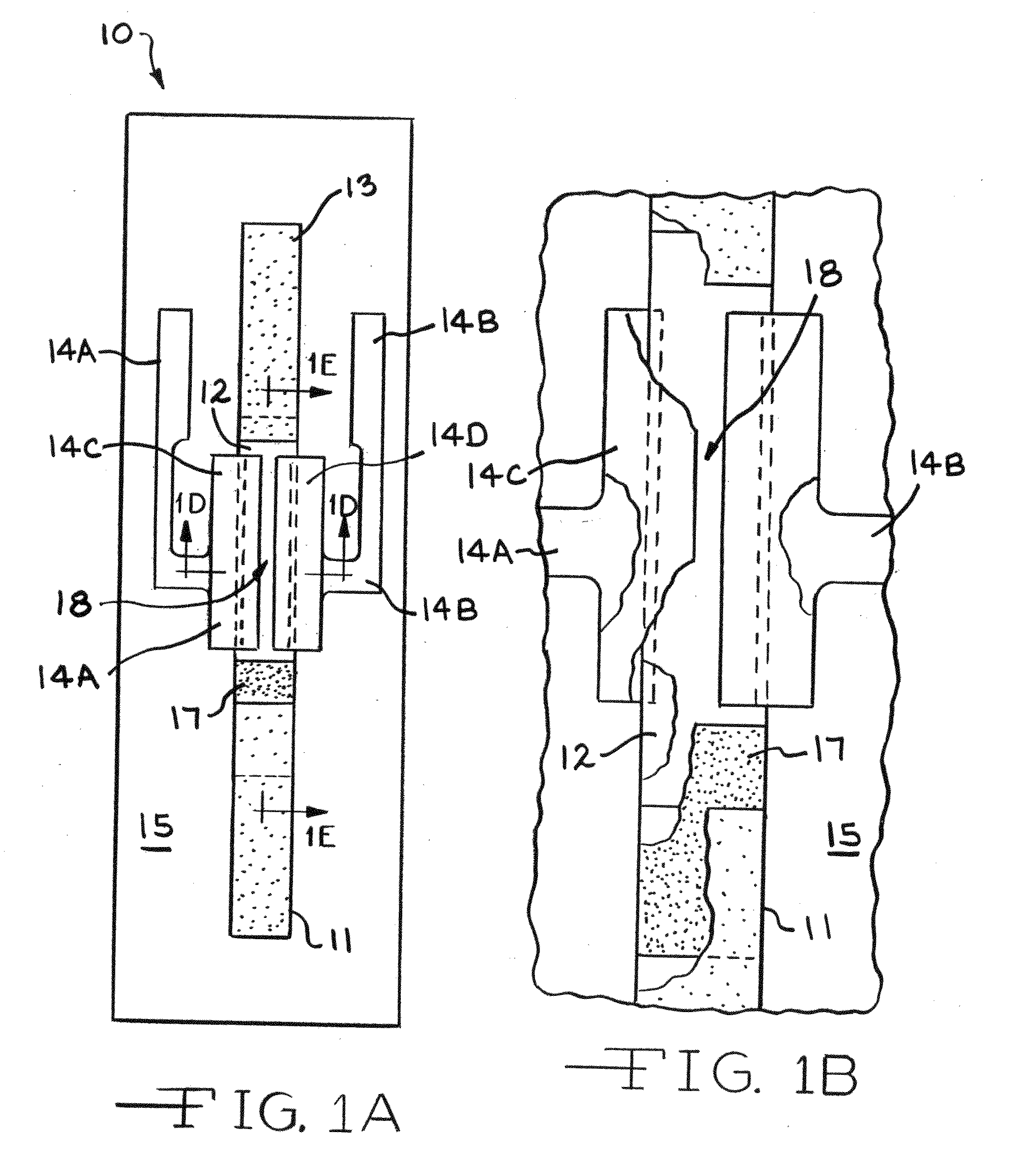
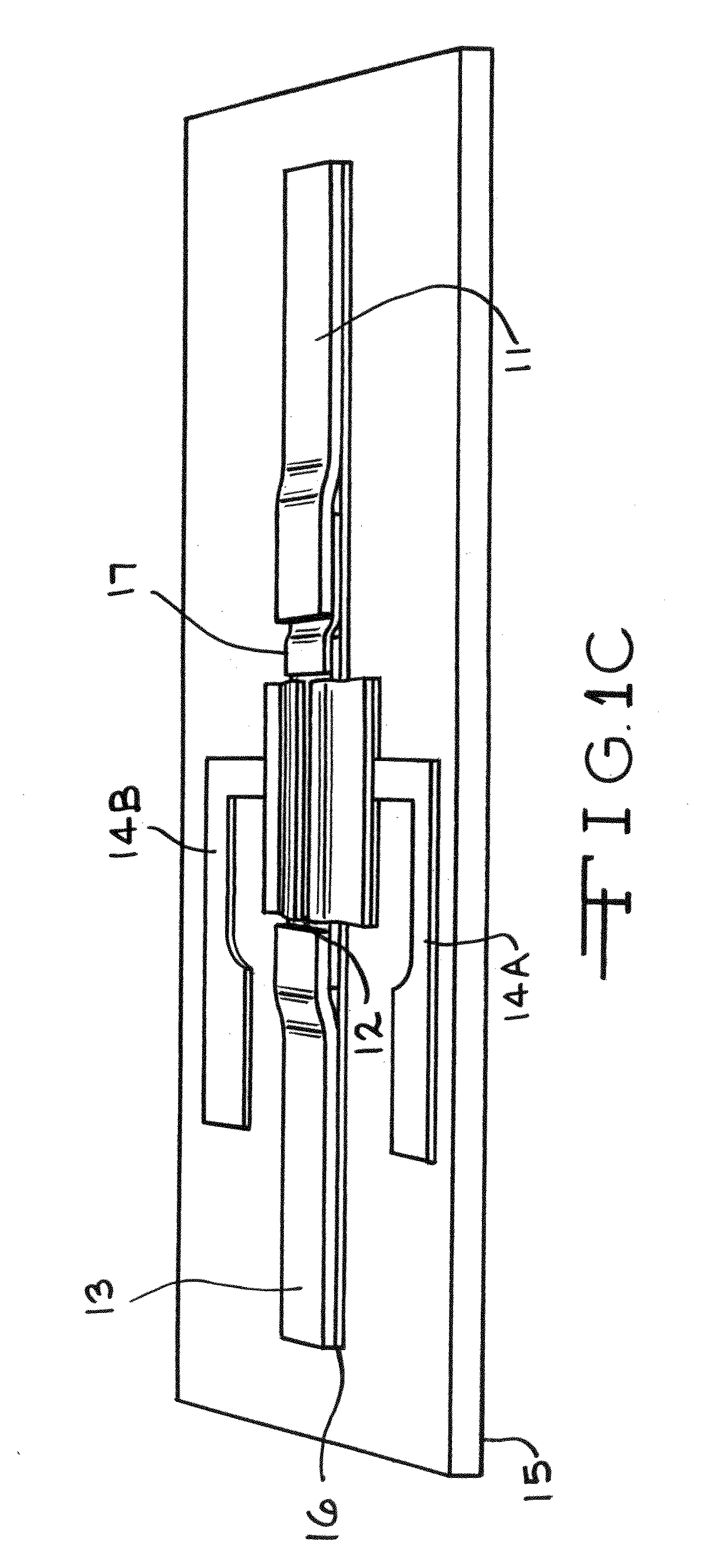
FIGS. 1 to 6A
Reagents:
[0045]Aniline, glutaraldehyde, N,N Dimethylformamide (DMF), Tween-20, tris buffer, phosphate buffer, phosphate buffer saline (PBS) were purchased from Sigma-Aldrich (Missouri). Antibodies (Rabbit anti-E. Coli 0157:H7) were obtained from Biodesign (Maine). Nitrocellulose (NC) membrane 12 with 8 μm pore size and flow rate of 160 sec per 4 cm, and cellulose membrane 13 were purchased from Millipore (Massachusetts). Fiber-glass membrane 11 grade G6 were also obtained from Millipore. Silver Kwik-stik pen for electrodes 14C and 14D was supplied from SPI (Pennsylvania). Other reagents used were of analytical grade. All chemicals and diluents were prepared with doubly deionized water with conductivity below 0.1 μS / cm.
Antibody Labeling with Polyaniline
[0046]A water-soluble polyaniline was synthesized with magnetic iron nanoparticles as the ferromagnetic particle by following a standard procedure of oxidative polymerization of aniline monomer in the presence of ammonium...
example 2
Construction of Multi-Array
[0092]More than one capture zone is designed on the NC capture membrane 20 as shown in FIG. 3, thus, multiple types of antibodies with different specificity can be immobilized on the membrane 20. FIG. 3 shows the design of the capture or signal region 23 with multiple regions 21A to 21D for antibody immobilization between electrodes 22A to 22E. As shown in FIG. 4, after sample application, the biosensor device 10 is inserted into the strip box 30. The lead wire 31 attached to the side of the box 30 induces a constant current from the power supply 32. The current flows across the capture or signal region 23 and generates a voltage signal 33, which is proportional to the changes of the resistance. The generated voltages are transferred through a circuit box 34 and stored in the computer 35 via the data acquisition 36.
examples 1 and 2
show:
[0093]1. A reduced distance between electrodes to preferably less than 500 μm in order to increase desired sensitivity to 1-10 cfu;
[0094]2. Improved membrane materials to reduce detection time to less than 2 min; and
[0095]3. A multi-array system for multiple and simultaneous detection.
PUM
| Property | Measurement | Unit |
|---|---|---|
| width | aaaaa | aaaaa |
| pore size | aaaaa | aaaaa |
| conductivity | aaaaa | aaaaa |
Abstract
Description
Claims
Application Information