Display device

a display device and display technology, applied in the field of display devices, can solve the problems of display defects, display degradation, and inability to obtain high reliability in the display device, and achieve the effects of high reliability, cost reduction, and material utilization efficiency

Inactive Publication Date: 2008-12-25
SEMICON ENERGY LAB CO LTD
View PDF20 Cites 19 Cited by
  • Summary
  • Abstract
  • Description
  • Claims
  • Application Information

AI Technical Summary

Benefits of technology

[0032]In an electrode layer used for a display element manufactured using a conductive composition containing a conductive polymer in accordance with the present invention, ionic impurities which contaminate a liquid crystal material, a light-emitting material, or the like which is used for a display element are reduced to 100 ppm or less. Therefore, a display device with high reliability can be manufactured using such an electrode layer.
[0033...

Problems solved by technology

However, there has been a problem such that if the above-described conductive polymer is used for an electrode layer in a display device or the like, high reliability cannot be obtained in the display device.
Mobile ionic impurities move in the display device and deteriorate a liquid crystal material or a l...

Method used


Image

  • Display device
  • Display device
  • Display device

Examples


embodiment mode 1

[0056]This embodiment mode will describe an example of a display device aimed at higher image quality and higher reliability, which can be manufactured at low cost with high productivity. Specifically, this embodiment mode will describe a display device having a passive-matrix structure.

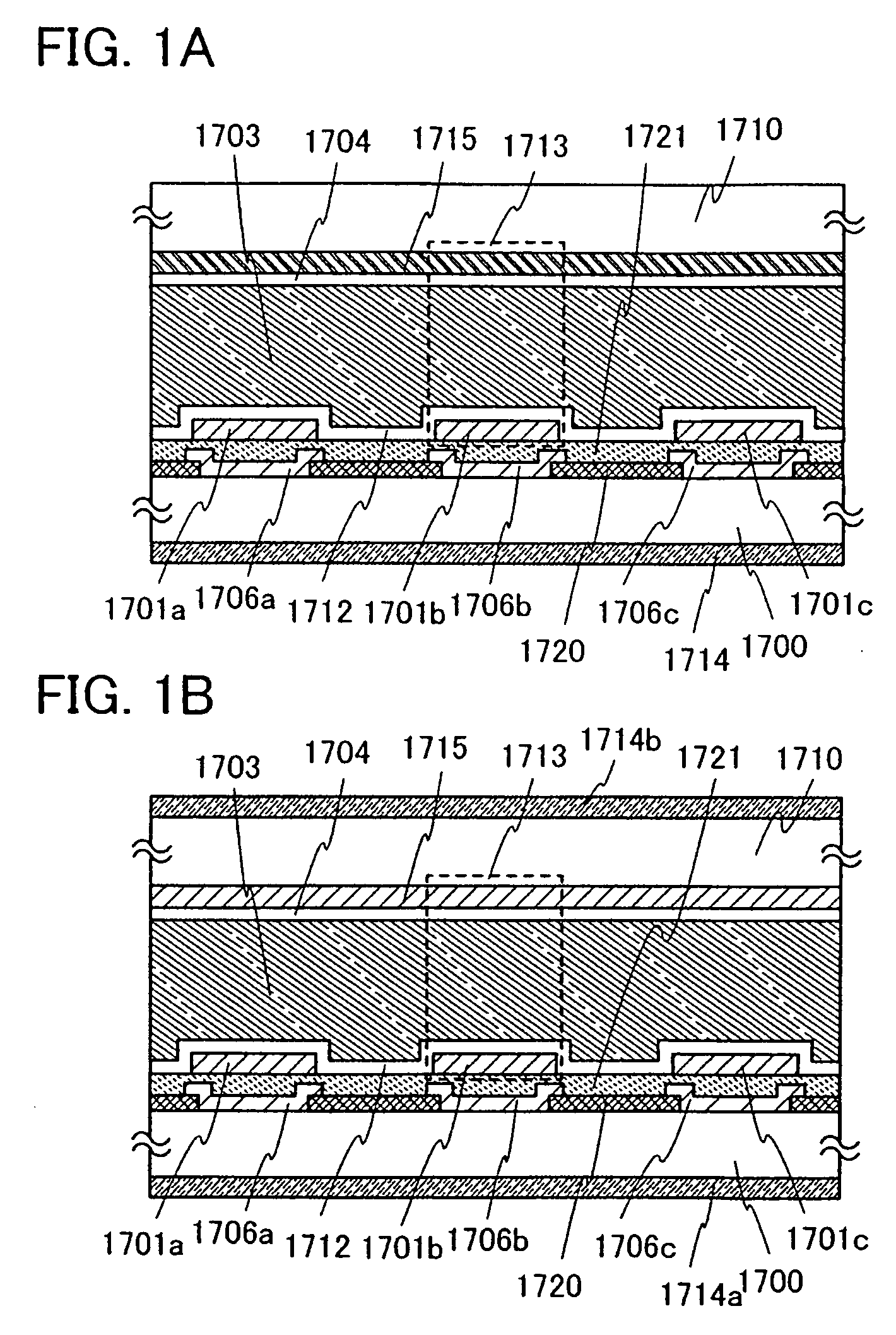
[0057]FIGS. 1A and 1B each show a passive matrix liquid crystal display device to which the present invention is applied. FIG. 1A illustrates a reflective liquid crystal display device and FIG. 1B illustrates a transmissive liquid crystal display device. In FIGS. 1A and 1B, a substrate 1700 provided with electrode layers 1701a, 1701b, and 1701c also referred to as pixel electrode layers, which are used for display elements 1713 and an insulating layer 1712 serving as an alignment film, color layers 1706a, 1706b, and 1706c serving as color filters, a polarizing plate 1714, and a light blocking layer 1720 is provided opposite to a substrate 1710 provided with an insulating layer 1704 serving as an alig...

embodiment mode 2

[0103]This embodiment mode will describe an example of a display device aimed at higher image quality and higher reliability, which can be manufactured at low cost with high productivity. In this embodiment mode, a display device having a structure different from the above-described display device in Embodiment Mode 1 will be described. Specifically, the case where the display device has an active matrix structure will be described.

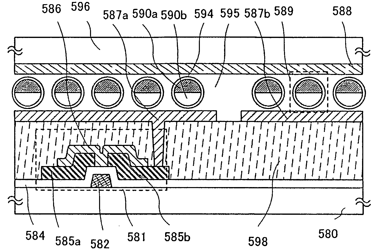
[0104]FIG. 5 shows a liquid crystal active matrix display device to which the present invention is applied. In FIG. 5, a substrate 550 provided with a transistor 551 having a multi-gate structure, an electrode layer 560 of a display element, and an insulating layer 561 serving as an alignment film, a substrate 568 provided with an insulating layer 563 serving as an alignment film, an electrode layer 564 of a display element, a color layer 565 serving as a color filter, a light blocking layer 570, an insulating layer 571, a spacer 572, a polarizer (also re...

embodiment mode 3

[0144]This embodiment mode will describe an example of a display device aimed at higher image quality and higher reliability, which can be manufactured at low cost with high productivity. Specifically, this embodiment mode will describe a liquid crystal display device using a liquid crystal display element as a display element.

[0145]FIG. 8A is a top view of a liquid crystal display device which is one mode of the present invention. FIG. 8B is a cross-sectional view taken along line C-D in FIG. 8A.

[0146]As shown in FIG. 8A, a pixel region 606 and driver circuit regions 608a and 608b which are scan line driver circuits are sealed between a substrate 600 and a counter substrate 695 with a sealing material 692. In addition, a driver circuit region 607 which is a signal line driver circuit including a driver IC is provided over the substrate 600. A transistor 622 and a capacitor 623 are provided in the pixel region 606, and a driver circuit including a transistor 620 and a transistor 621...


PUM


Abstract

To provide display devices with improved image quality and reliability or display devices with a large screen at low cost with high productivity, an electrode layer containing a conductive polymer is used as an electrode layer for a display element, and the concentration of ionic impurities contained in the electrode layer containing a conductive polymer is reduced (preferably to 100 ppm or less). Ionic impurities are ionized, and easily become mobile ions, and they deteriorate a liquid crystal layer or an electroluminescent layer, which is used for a display element. Therefore, an electrode layer containing a conductive polymer, in which such ionic impurities are reduced is provided; thus, reliability of the display device can be improved.

Description

TECHNICAL FIELD[0001]The present invention relates to display devices including a display element which includes electrode layers.BACKGROUND ART[0002]Conductive polymers are widely used as a conductive material or an optical material for various devices in the electrical and electronics industry because of their high processability. Novel conductive polymer materials / materials of conductive polymers are developed to improve conductivity and processability of a conductive polymer for practical application.[0003]For example, an alkali metal, a halogen, or the like is added to a conductive polymer as a dopant in order to improve conductivity (for example, see Reference 1: Japanese Published Patent Application No. 2003-346575).DISCLOSURE OF INVENTION[0004]However, there has been a problem such that if the above-described conductive polymer is used for an electrode layer in a display device or the like, high reliability cannot be obtained in the display device.[0005]Therefore, it is an o...

Claims


Application Information

Patent Timeline
IPC IPC(8): G02F1/1343
CPCC09K19/582G02F1/13439G02F2202/022G02F2202/16H01L51/0021H01L51/0025H01L51/5206H01L51/5221H10K71/311H10K71/60H10K59/8051H10K59/8052H05B33/26H10K50/81H10K50/82
Inventor FUJII, GENTAKAHASHI, ERIKA
Owner SEMICON ENERGY LAB CO LTD
Why Eureka
Try Eureka