Planar surface plasmon resonance detector

Inactive Publication Date: 2008-12-25
NATIONAL TSING HUA UNIVERSITY
View PDF2 Cites 37 Cited by
  • Summary
  • Abstract
  • Description
  • Claims
  • Application Information

AI Technical Summary

Benefits of technology

[0013]Besides, the present invention may further comprise an adhesive layer between the glass substrate and the metallic detection film. The adhesive layer is an about 3 nm thick film made of t

Problems solved by technology

However, not all interfaces can have surface plasmon resonance.
Owing to the high-priced monochromatic light source and the expensive high-refr

Method used


Image

  • Planar surface plasmon resonance detector
  • Planar surface plasmon resonance detector
  • Planar surface plasmon resonance detector

Examples


Example

[0020]The technical contents of the present invention will be described in detail with the embodiments. However, it should be noted that the embodiments are only to exemplify the present invention but not to limit the scope of the present invention.

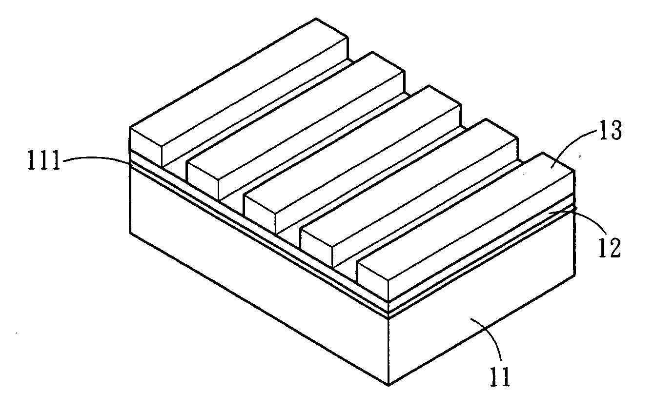
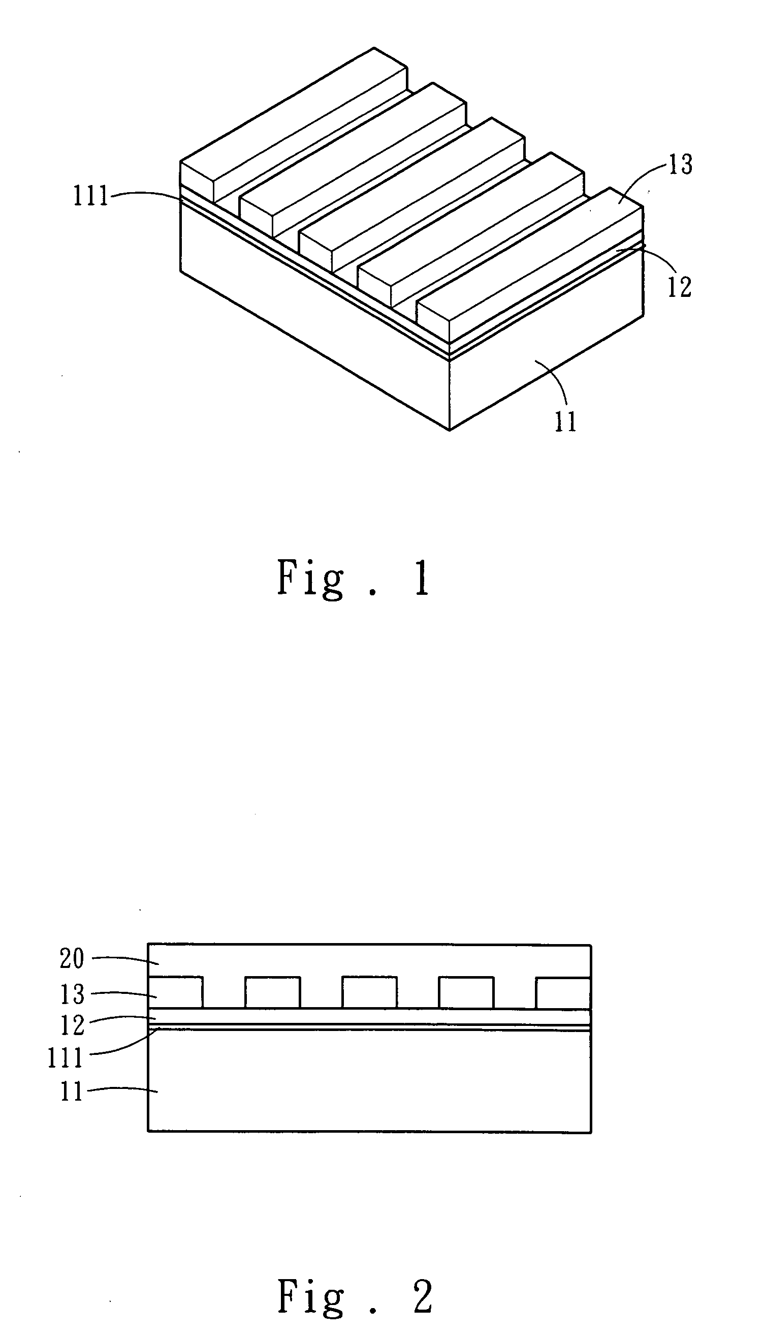
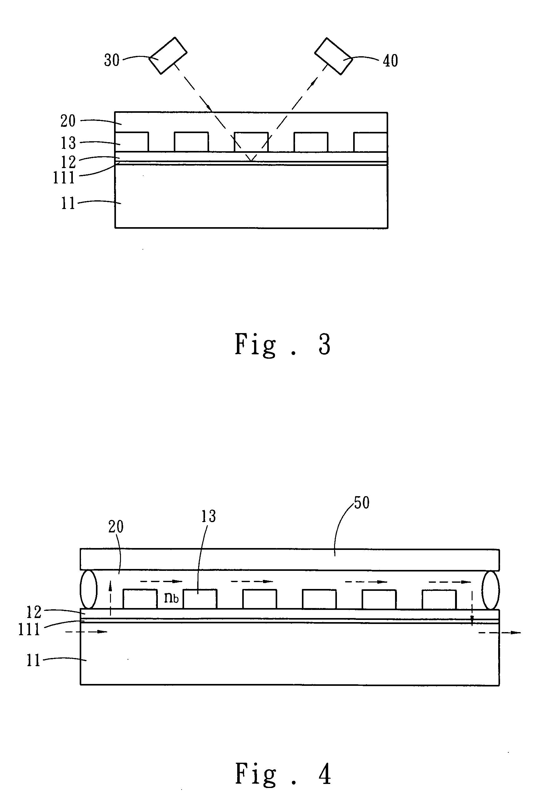
[0021]Refer to FIG. 1 a diagram schematically showing the planar SPR detector according to the present invention. The planar SPR detector of the present invention comprises a glass substrate 11, a metallic detection film 12 arranged on the glass substrate 11, a metallic grating structure 13 on the metallic detection film 12. As shown in FIG. 2, a sample-containing liquid 20 (the liquid containing the material to be tested) is disposed on the metallic detection film 11 and the metallic grating structure 13 to generate surface plasmon resonance. The metallic detection film 12 is a gold film, a silver film, or a copper film. Alternatively, the metallic detection film 12 may be formed via depositing a gold film over a silver film. The metalli...


PUM


Abstract

The present invention discloses a planar surface plasmon resonance detector, wherein a periodic metallic grating structure is arranged on a common glass substrate to replace prisms and generate surface plasmon resonance. The shift of the wavelength or incident angle for surface plasmon resonance is used to detect biochemical molecules. Further, a low-cost white light-emitting diode replaces laser to function as a light source. Via the metallic grating structure and the white light-emitting diode, the present invention can facilitate a low-cost, compact and portable planar surface plasmon resonance detector and popularize the planar surface plasmon resonance detector.

Description

FIELD OF THE INVENTION[0001]The present invention relates to a plasmon resonance detector, particularly to a planar surface plasmon resonance detector, which adopts a white light-emitting diode as a light source and replaces prisms with a grating structure to induce surface plasmon resonance.BACKGROUND OF THE INVENTION[0002]Surface plasmon resonance is a phenomenon: when a light beam hits on a metallic surface at a specified incident angle, the intensity of the reflected light detected by a light detector is near zero, i.e. the reflectivity is near zero, and the non-reflected light travels along the direction parallel to the interface and induces the so-called surface plasmon resonance (SPR). Surface plasmon resonance is usually induced by an ATR (Attenuated Total Reflection) method, wherein a light beam reaches a metallic film via prisms at an incident angle greater than the total-reflection angle, and the intensity of the reflected light is near zero at a specified angle.[0003]SPR...

Claims


Application Information

Patent Timeline
IPC IPC(8): G01N21/55
CPCG01N21/554G01N21/7743
Inventor YEN, TA-JENLI, CHUNG-TIENCHANG, HSIN-YUNGUAN, YOU-LUN
Owner NATIONAL TSING HUA UNIVERSITY
Why Eureka
Try Eureka