
Apparatus and method for two wave mixing (TWM) based ultrasonic laser testing

a technology of ultrasonic laser and two wave mixing, applied in the direction of measurement devices, instruments, scientific instruments, etc., can solve the problems of adversely increasing the manufacturing cost associated with composite structures, labor-intensive, expensive, and difficult to achieve the effect of reducing the number of instruments, improving the signal-to-noise ratio, and flexible distribution of the different devices

Active Publication Date: 2008-12-25
LOCKHEED MARTIN CORP
View PDF12 Cites 25 Cited by
  • Summary
  • Abstract
  • Description
  • Claims
  • Application Information

AI Technical Summary

Benefits of technology

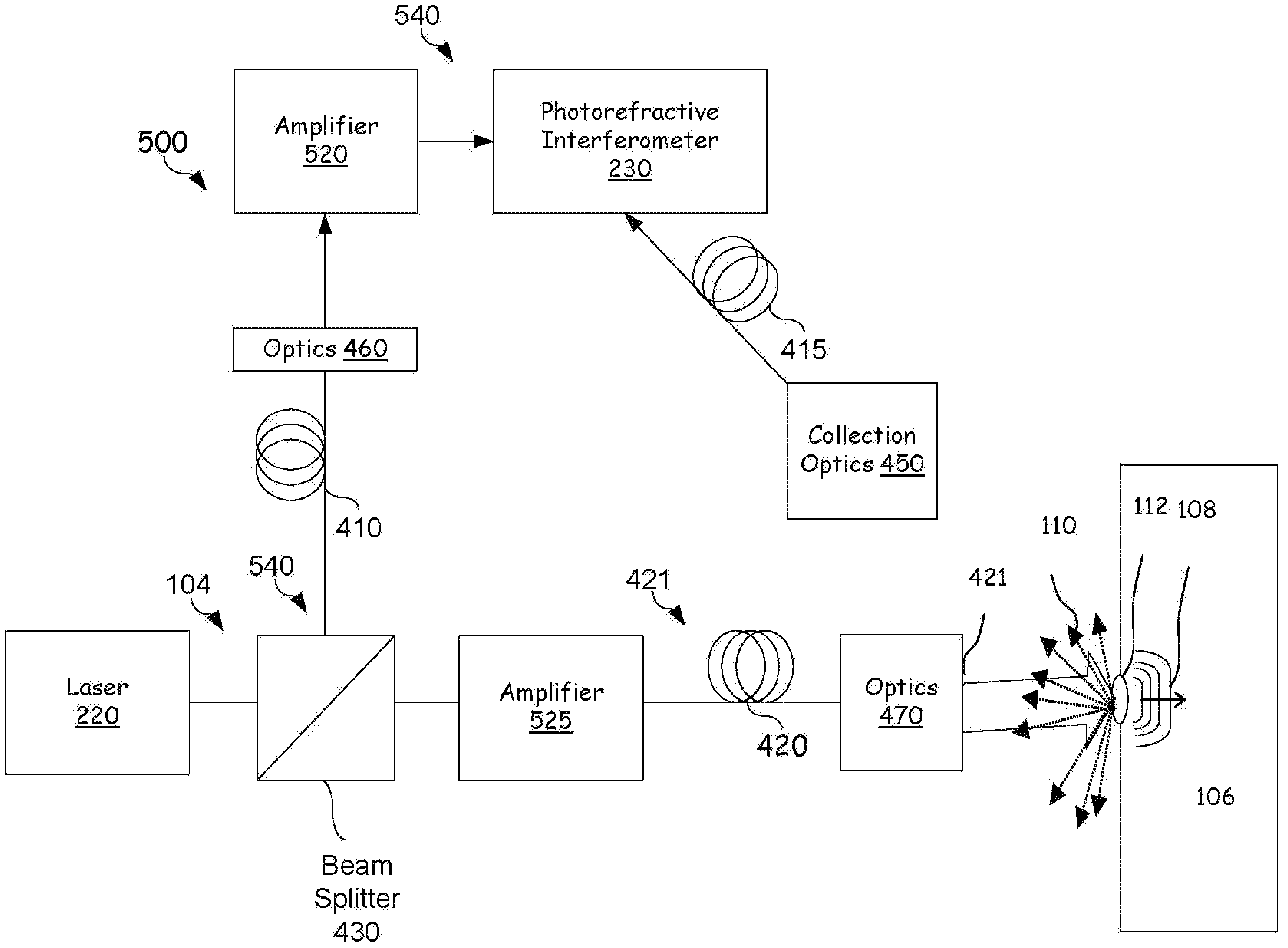
[0017]A technical advantage of the present invention is that an improved method for ultrasonic laser testing is provided that allows for more efficient distribution of the different devices in a laser-ultrasonic testing system than prior art such systems. The present invention further provides for independent control of the laser power provided in the pump beam, allowing for desired photorefractive crystal speeds and improved signal-to-noise ratios. The present invention provides a flexible, accurate and cost effective method for inspecting complex composite structures.
is that an improved method for ultrasonic laser testing is provided that allows for more efficient distribution of the different devices in a laser-ultrasonic testing system than prior art such systems. The present invention further provides for independent control of the laser power provided in the pump beam, allowing for desired photorefractive crystal speeds and improved signal-to-noise ratios. The present invention provides a flexible, accurate and cost effective method for inspecting complex composite structures.

Problems solved by technology

While composite materials offer significant improvements in performance, they require strict quality control procedures in both the manufacturing processes and after the materials are in service in finished products.
Conventional NDE methods are slow, labor-intensive, and costly.
As a result, testing procedures adversely increase the manufacturing costs associated with composite structures.
However, one difficulty with the TWM interferometer is that it requires a reference (or pump) beam in addition to a probe (detection) beam to work.
These peak powers make the transmission of the pump beam through an optical fiber difficult over large distances due to effects like stimulated Brillouin scattering.
However, such an effective proximity cannot be easily obtained for scanning systems where the space around the detection laser is limited.
The injection of a high peak power pump beam into an optical fiber is also a concern because the optical fiber can be damaged by the high powered beam if a misalignment occurs.
Another problem with having a high power pump beam is that power must be diverted from the probe beam to supply the pump beam.
Therefore, the detection laser power diverted into the pump beam decreases the quality of the ultrasonic signals.
Further, in existing TWM interferometer laser ultrasonic detection systems, the level of pump beam power cannot be controlled independently of the probe beam power and the power of the pump beam influences the time-response of the photorefractive crystal and also contributes to background noise on the detector.

Method used


Image

  • Apparatus and method for two wave mixing (TWM) based ultrasonic laser testing
  • Apparatus and method for two wave mixing (TWM) based ultrasonic laser testing
  • Apparatus and method for two wave mixing (TWM) based ultrasonic laser testing

Examples


Embodiment Construction

[0024]Preferred embodiments of the present invention are illustrated in the FIGs., like numerals being used to refer to like and corresponding parts of the various drawings.

[0025]Embodiments of the present invention provide an improved system, apparatus and method for ultrasonic laser testing using an independently-amplified two wave mixing (TWM) interferometer reference (pump) beam. Unlike prior art ultrasonic laser testing systems using a TWM interferometer, the embodiments of the present invention can thus provide an independent way to control the power of the pump beam to obtain desired photorefractive crystal speeds and background noise levels. The embodiments of the present invention can significantly reduce the amount of power diverted from the detection laser beam to improve the signal-to-noise ratio of the detected ultrasonic signals. Further, embodiments of the present invention provide for a more reliable coupling of the pump beam into an optical fiber and provide for mor...


PUM


Abstract

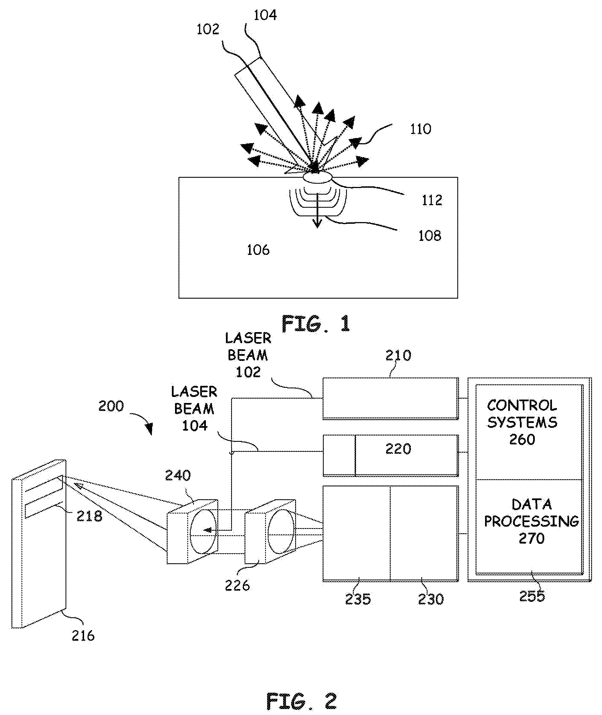
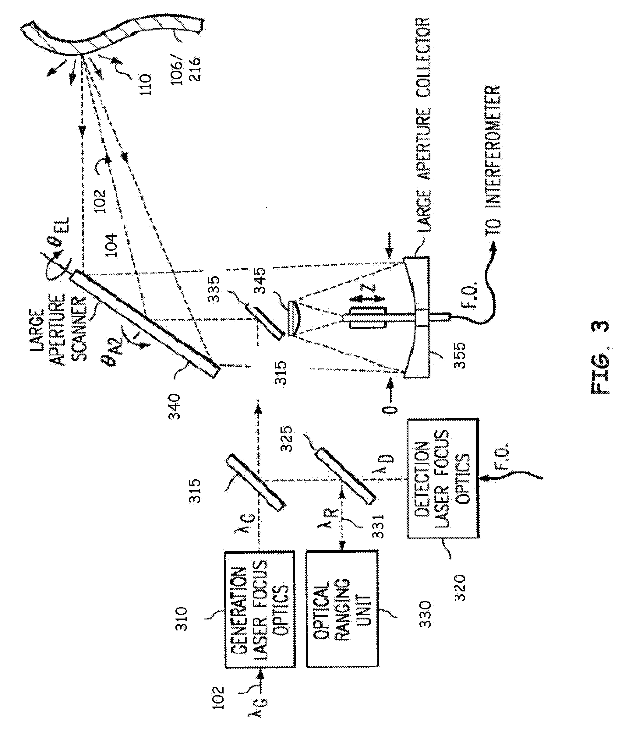
A system and method for detecting ultrasonic surface displacements at a remote target are disclosed, one embodiment of the system comprising: a first laser to generate a first laser beam. The first laser beam produces ultrasonic surface displacements on a surface of the remote target. A second laser generates a second laser beam operable to detect the ultrasonic surface displacements on the surface of the remote target and to provide a reference beam to an interferometer. The second laser beam is split, at a beam-splitter, into a pump beam and a probe beam. The pump beam is amplified by a first amplifier and the probe beam is amplified by a second amplifier. The pump beam is then provided to the interferometer as a reference beam and the probe beam is directed to the target to detect the ultrasonic surface displacements. The first and second amplifiers can be controlled independently of one another to control their respective laser beam's power. Collection optics collect phase modulated light from the probe beam either reflected or scattered by the remote target, which can be optionally optically processed to increase the light intensity. The interferometer is a TWM interferometer that receives and processes the phase modulated light and generates at least one output signal based on the phase-modulated light and the amplified reference laser beam.

Description

RELATED APPLICATIONS[0001]This application incorporates by reference and claims the benefit of U.S. Provisional Application No. 60 / 091,240 filed on 30 Jun. 1998 for all purposes.[0002]This application incorporates by reference and claims the benefit of U.S. Provisional Application No. 60 / 091,229 filed on 30 Jun. 1998 entitled “METHOD AND APPARATUS FOR DETECTING ULTRASONIC SURFACE DISPLACEMENTS USING POST-COLLECTION OPTICAL AMPLIFICATION” to Thomas E. Drake.[0003]This application incorporates by reference and claims the benefit of U.S. patent application Ser. No. 10 / 753,208 filed on 7 Jan. 2004 and entitled “REMOTE LASER BEAM DELIVERY SYSTEM AND METHOD FOR USE WITH A ROBOTIC POSITIONING SYSTEM FOR ULTRASONIC TESTING PURPOSES” to Thomas E. Drake.[0004]This application incorporates by reference and claims the benefit of U.S. patent application Ser. No. 10 / 634,342 filed on 12 Feb. 2004 and entitled “METHOD AND APPARATUS FOR ULTRASONIC LASER TESTING” to Thomas E. Drake.TECHNICAL FIELD OF...

Claims


Application Information

Patent Timeline
IPC IPC(8): G01B9/02
CPCG01N29/2418G01N2291/0231G01B9/02083G01B2290/65
Inventor DRAKE, JR., THOMAS E.DUBOIS, MARC
Owner LOCKHEED MARTIN CORP
Learn More