Nanoparticle ultracapacitor

Inactive Publication Date: 2008-12-25
TANGREDI PATRICIA
View PDF28 Cites 86 Cited by
  • Summary
  • Abstract
  • Description
  • Claims
  • Application Information

AI Technical Summary

Benefits of technology

[0010]Particular aspects provide an energy storage device or capacitor, comprising at least three layers that are sealed in a fluid-tight covering, wherein a first layer comprises at least one electrolytic polymer molecule of positive charge and at least one nanoparticle; a second dielectric layer comprising at least one insulative polymer; a third layer comprising at least one electrolytic polymer molecule of negative charge and at least one nanoparticle. In certain embodiments, the electrolytic polymer of the first layer comprises at least one high charge density polymer electrolyte of positive charge, and wherein the electrolytic polymer of the third layer comprises at least one high charge density polymer electrolyte of negative charge. In particular aspects, the nanoparticles comprise electrically conductive nanoparticles. In certain embodiments, the electrically conductive nanoparticles comprise at least one component selected from the group consisting of nickel, carbon, titanium dioxide, lead, lithium, silver, copper, phthalocyanine oligomers, electrically conductive molecules and electrically conductive particles. In certain aspects, the at least one nanoparticle of at least one layer comprises carbon. In certain embodiments, the second, dielectric layer comprises barium titanate. In particular aspects, the second, dielectric layer further comprises at least one nanoparticle. In particular aspects, the second, dielectric layer comprises a mixture of cationic and anionic exchange molecules or electrolytic polymers mixed with a metal oxide. In particular aspects, the second, dielectric layer comprises at least one nanoparticle coate

Problems solved by technology

Batteries have limited ability to be recycled and cannot deliver energy as quickly as a capacitor, or without greater losses than occurs with capacitors.
However, the carbon powder tends to accumulate at specific points on the electrodes, rather than stay

Method used


Image

  • Nanoparticle ultracapacitor
  • Nanoparticle ultracapacitor
  • Nanoparticle ultracapacitor

Examples


examples

[0099]The following table indicates specific properties of one particular exemplary embodiment, compared with other capacitors or batteries in use today.

DaisMaxwellA123UltracapUltracapEEStorLithium ion(estimated)(spec sheet)UltracapbatteryEnergy Density600 (1)15 (2)700 (11)400 (3)(Wh / L)Specific Energy200 (1)4 to 6 (2)290 (11)150 (3)Wh / kgSelf Discharge2% / month (4)50% / month (5)0.02% / month (11)2% / month (3)RateSpecific Power>1500 (1, 6)>1500 (5)106 (11)200-400 (9)W / kgESR100 m-Ohm (6)65 m-Ohm (5)22 u-Ohm (11)11 Ohm (7)Storage−40 to +125 (8)−40 to +65 (2)??−50 to +60 (3)Temp Range (° C.)Operating−40 to +85 (8)−40 to +65 (2)−40 to +85 (11)−30 to +60 (3)Temp Range (° C.)Cyclic>10,000 (10)>500,000 (2)>1,000,000 (11)>1000 (3)Lifetime

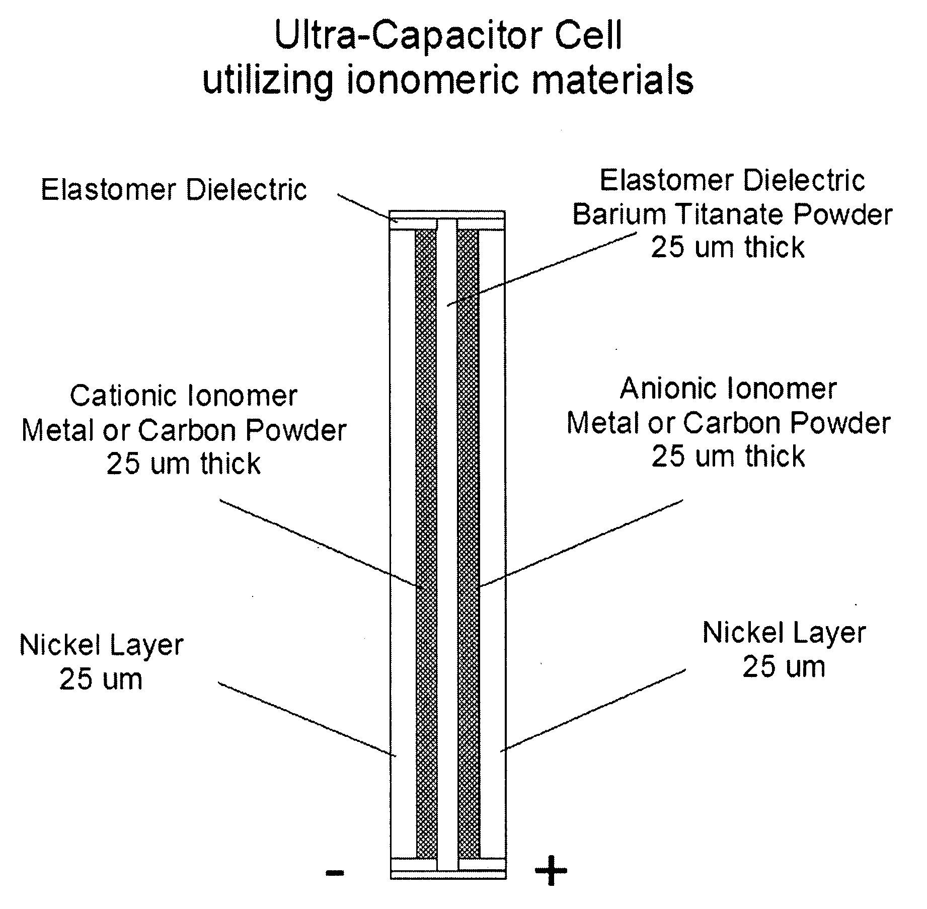
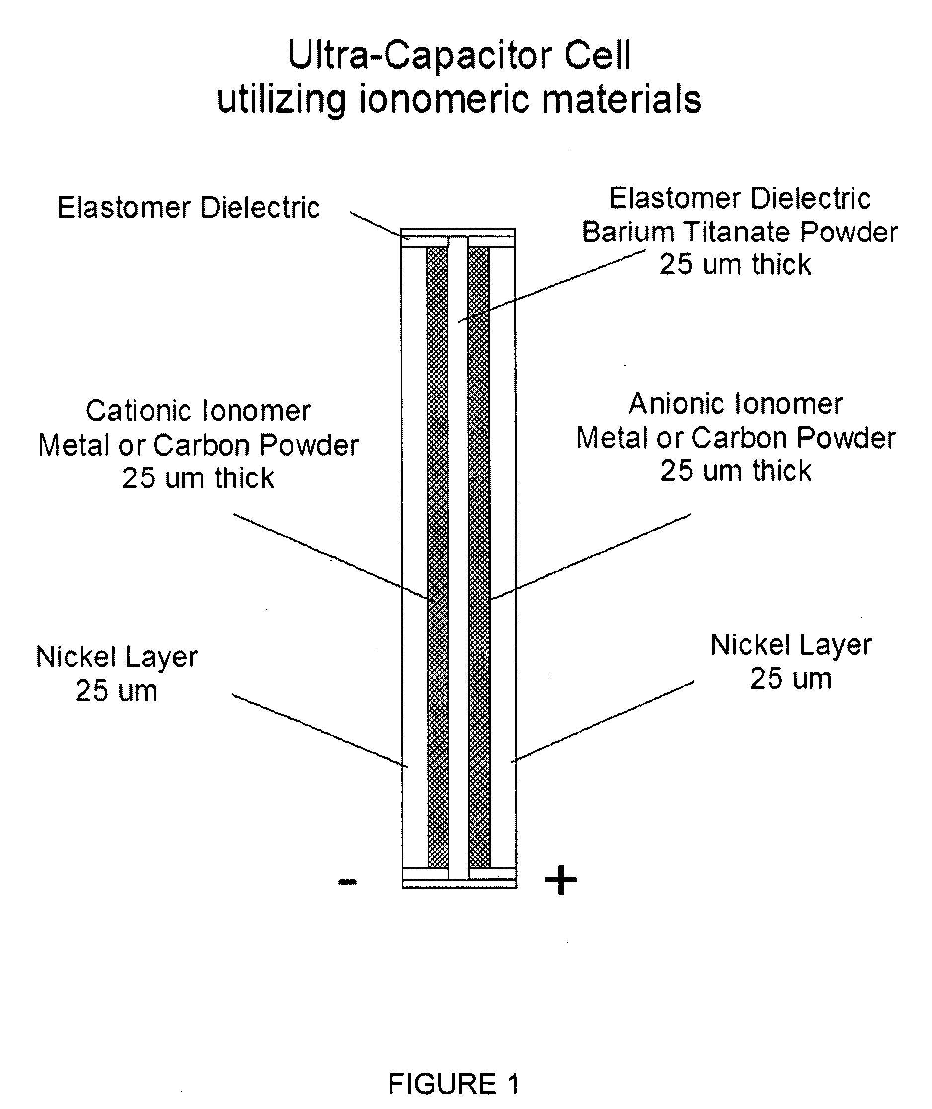
Thus, preferred embodiments disclosed herein include capacitors of a 5-7 layer structure capable of sustaining voltages in excess of 3 volts per cell with an upper maximum of several thousand volts per cell. Certain preferred embodiments include a capacitor that i...


PUM

PropertyMeasurementUnit
Percent by massaaaaaaaaaa
Thicknessaaaaaaaaaa

Abstract

Particular aspects provide capacitors, and particularly ultracapacitors, comprising molecules suitable to substantially increasing the capacitance of the capacitor, and methods for making same Particular aspects provide ultracapacitors that include nanoparticles optionally coated with molecules, such as polymer electrolytes. Certain aspects provide an energy storage device or capacitor, comprising at least three layers sealed in a fluid-tight covering, wherein a first layer comprises at least one electrolytic polymer molecule of positive charge and at least one nanoparticle; a second dielectric layer comprising at least one insulative polymer; a third layer comprising at least one electrolytic polymer molecule of negative charge and at least one nanoparticle. In certain aspects, the electrolytic polymer of the first layer comprises at least one high charge density polymer electrolyte of positive charge, and wherein the electrolytic polymer of the third layer comprises at least one high charge density polymer electrolyte of negative charge.

Description

CROSS-REFERENCE TO RELATED APPLICATION[0001]This application claims benefit under 35 U.S.C. § 119(e) of U.S. Provisional Application Ser. No. 60 / 830,583, filed Jul. 14, 2006, the content of which is hereby incorporated by reference in its entirety.FIELD OF THE INVENTION[0002]The present disclosure relates to a molecular capacitor, and particularly a molecular electrolytic capacitor, and methods of manufacturing the same.BACKGROUND[0003]Electrical energy storage devices, such as capacitors, batteries, and ultracapacitors, store or create energy by utilizing the electric charge on two metal or otherwise electrically conductive surfaces (“electrodes”). The charge-bearing surfaces are typically separated by an electrical insulator, or dielectric. As charge is placed on the conductive surfaces, an electrical field is established between the electrodes, resulting in a voltage. Typically, a capacitor physically separates positive and negative charges, rather than chemically separating the ...

Claims


Application Information

Patent Timeline
IPC IPC(8): H01G9/00
CPCH01G9/058H01G9/155H01G11/36H01G11/46Y02E60/13Y02T10/7022Y10T29/417Y10T29/435Y02T10/70H01G11/22H01G11/84H01G11/12
Inventor EHRENBERG, SCOTT G.CAO, LIWEI
Owner TANGREDI PATRICIA
Why Eureka
Try Eureka