
Optic fiber bragg grating sensor

a technology of optical fiber bragging and optical fiber, applied in the direction of fluid pressure measurement, fluid pressure measurement by electric/magnetic elements, instruments, etc., can solve the problems of electronic pressure sensors or electronic displacement sensors that are not of distributed design, electronic signals may be affected by electromagnetic interference (emi), and are prone to destruction. to achieve the effect of enhancing the sensitivity of the measuring devi

Inactive Publication Date: 2008-12-25
NAT CHIAO TUNG UNIV
View PDF1 Cites 18 Cited by
  • Summary
  • Abstract
  • Description
  • Claims
  • Application Information

AI Technical Summary

Benefits of technology

"The present invention provides an FBG sensor with a chirped or differential design that is independent from temperature variations. The sensor can be used for a variety of purposes such as gauge pressure transducer, differential pressure transducer, load cell, and displacement transducer. The sensor includes an elastic circular diaphragm with one or two FBG's attached to its surface. The FBG's are aligned with the neutral axis of the diaphragm and the sensor can provide accurate and reliable measurements even with multiple sensors connected in series on a single optic fiber. The sensor is also sensitive to physical quantities and can be adjusted to measure a range of quantities by varying the diameter and / or thickness of the diaphragm."

Problems solved by technology

Meanwhile, most electronic pressure sensors or electronic displacement sensors are of non-distributive design.
Therefore, the applications of such sensors are often limited by the number of transmission lines that can be accommodated in the system.
Furthermore, the electronic signal may be affected by electromagnetic interference (EMI) and prone to destruction by lightning when applied in the field.
An important disadvantage of this design is that the reading has to be compensated for temperature variation.
A disadvantage of this design is that the cantilever beam cannot be used to isolate the pressure chamber.
The designs are more complex, and the sensitivity and linearity are compromised.

Method used


Image

  • Optic fiber bragg grating sensor
  • Optic fiber bragg grating sensor
  • Optic fiber bragg grating sensor

Examples


Embodiment Construction

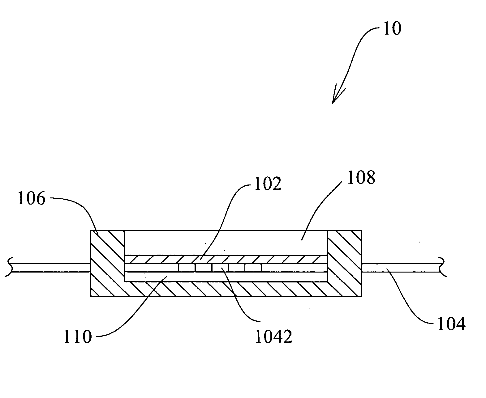
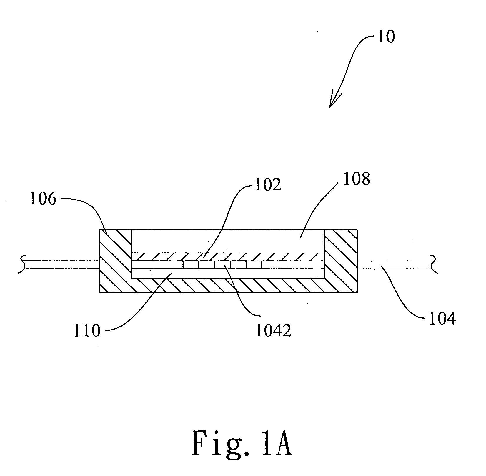
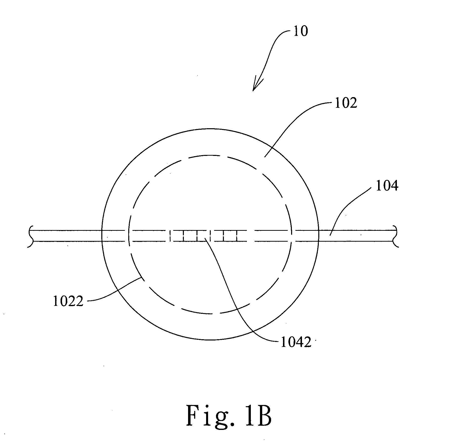
[0019]The present invention proposes attaching a single or two FBG on one side of an elastic circular diaphragm with a fixed edge. FIG. 1A and FIG. 1B are a cross-sectional schematic diagram and a bottom-view schematic diagram respectively illustrating the FBG sensor 10 according to an embodiment of the present invention. As shown in FIGS. 1A and 1B, the FBG sensor 10 includes an elastic circular diaphragm 102; and the optical fiber 104 located below the elastic circular diaphragm 102 for signals transmission. The optical fiber 104 includes at least one FBG 1042 attached on the bottom surface of the elastic circular diaphragm 102.

[0020]In an embodiment, the FBG sensor 10 further comprises a rigid shell 106, and the elastic circular diaphragm 102 and the FBG 1042 are set inside the rigid shell 106. The optical fiber 104 is passed through the rigid shell 106. In an aspect of the present invention, a space 108 located on top of the elastic circular diaphragm 102 inside the rigid shell ...


PUM


Abstract

The optic fiber Bragg grating (FBG) sensor comprises of an elastic circular diaphragm and one or two FBG attached to the bottom surface of the elastic circular diaphragm. Two ends of the FBG are connected to an optic fiber for signal transmission. The FBG sensor readouts are independent of temperature fluctuation. The FBG sensor mechanism according to the present invention may be applied for various purposes such as a gauge pressure transducer, differential pressure transducer, load cell and displacement transducer with distributive capabilities.

Description

BACKGROUND OF THE INVENTION[0001]1. Field of the Invention[0002]The present invention generally relates to an optic fiber Bragg grating(FBG) sensor, and more particularly relates to an optic fiber Bragg grating sensor applied as a gauge pressure transducer, differential pressure transducer, load cell, and displacement transducer.[0003]2. Description of the Prior Art[0004]Conventionally, most electronic pressure sensors or electronic displacement sensors transform the applied physical quantity into an electrical current or voltage signal via various means (e.g., resistance or vibrating wire strain gages or LVDT) to facilitate the data acquisition.[0005]Meanwhile, most electronic pressure sensors or electronic displacement sensors are of non-distributive design. Each sensing unit needs an individual signal transmission line. Therefore, the applications of such sensors are often limited by the number of transmission lines that can be accommodated in the system. Furthermore, the electro...

Claims


Application Information

Patent Timeline
Patent Type & Authority Applications(United States)
IPC IPC(8): G02B6/10
CPCG01D5/35303G01L9/0076G01L11/025G02B6/022G01D5/35316
Inventor HUANG, AN-BINKAO, SHENG-CHIANG
Owner NAT CHIAO TUNG UNIV
Learn More