Method for recycling of synthetic material containing waste

a synthetic material and waste technology, applied in the field of synthetic material recycling, can solve the problems of large waste disposal problems of synthetic materials containing wastes, further significant cosub>2 /sub>emissions harmful to the climate, and achieve the effects of avoiding crack formation, limiting the structural stability of slopes, and high sorption behaviour

Inactive Publication Date: 2008-12-25
KUGLER DIPL ING JOST ULRICH
View PDF3 Cites 6 Cited by
  • Summary
  • Abstract
  • Description
  • Claims
  • Application Information

AI Technical Summary

Benefits of technology

[0017]Drying or dehydration, respectively of mineral sealing soils usually results in cracks that cancel the sealing effect. Against this, according to the prior art, sealing systems are superimposed with reinforcing meshes or sealing systems with a superimposed floating soil of the soil class DIN 18 300, class 2, floating soil type for a self-repairing effect which limits the structural stability of slopes.
[0018]Alternatively to mineral sealings, also top soil layers with a thickness of 1.50 m to 2.00 m are applied to landfill surfaces with high sorption behaviour against rain water so that by the soil of 2.00 m thickness a rejection of rain water against the body of the landfill should occur. The problem of the crack formation due to dehydration can however be avoided by the addition of crushed synthetic material containing waste, preferabl

Problems solved by technology

Synthetic material containing wastes are a great waste disposal problem.
However, in this process even in the case of an optimized incineration in a modern plant a very large quantities of CO2 emissions harmful to the climate are generated as is shown by the following estimation: At a usual content of approximately 50% to 70% of TOC (saturated total organic carbon) of the synthetic material containing waste at the oxidation (incineration) the following reaction takes place: C+O2→CO2.
In addition, in waste incineration plants often overheating arise due to the addition of well inflammable synthetic material containing waste which the waste incineration plants to do not tol

Method used


Image

  • Method for recycling of synthetic material containing waste
  • Method for recycling of synthetic material containing waste

Examples


Embodiment Construction

[0023]In the following initially fields of application of the inventive method are generally explained then special embodiments are exemplified for consolidation. It shall be understood that aspects of an individual embodiment can also be applied in other embodiments even if this is not explicitly mentioned. On the other hand not all features of the method explained in the context of a following embodiment are mandatory for the execution of the method.

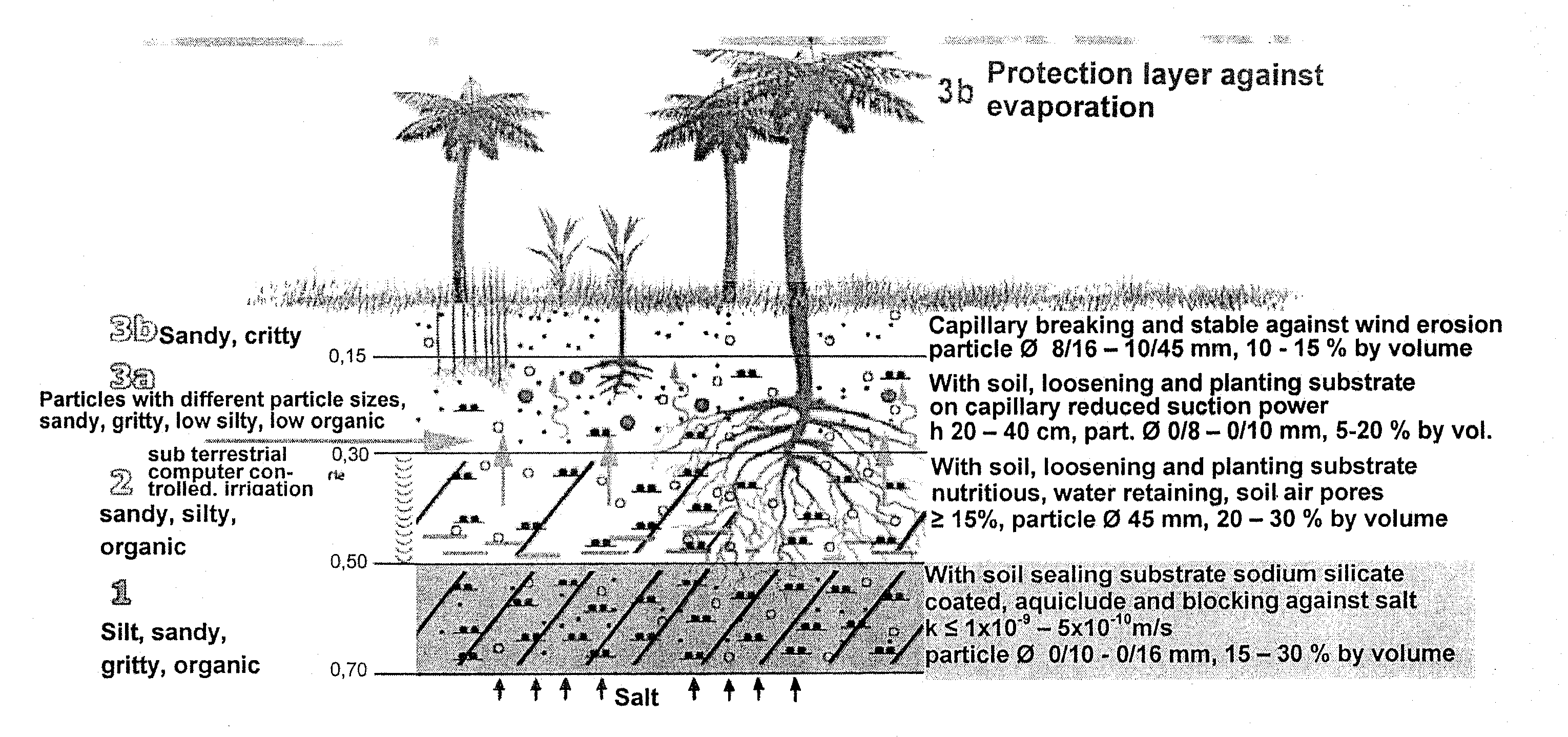
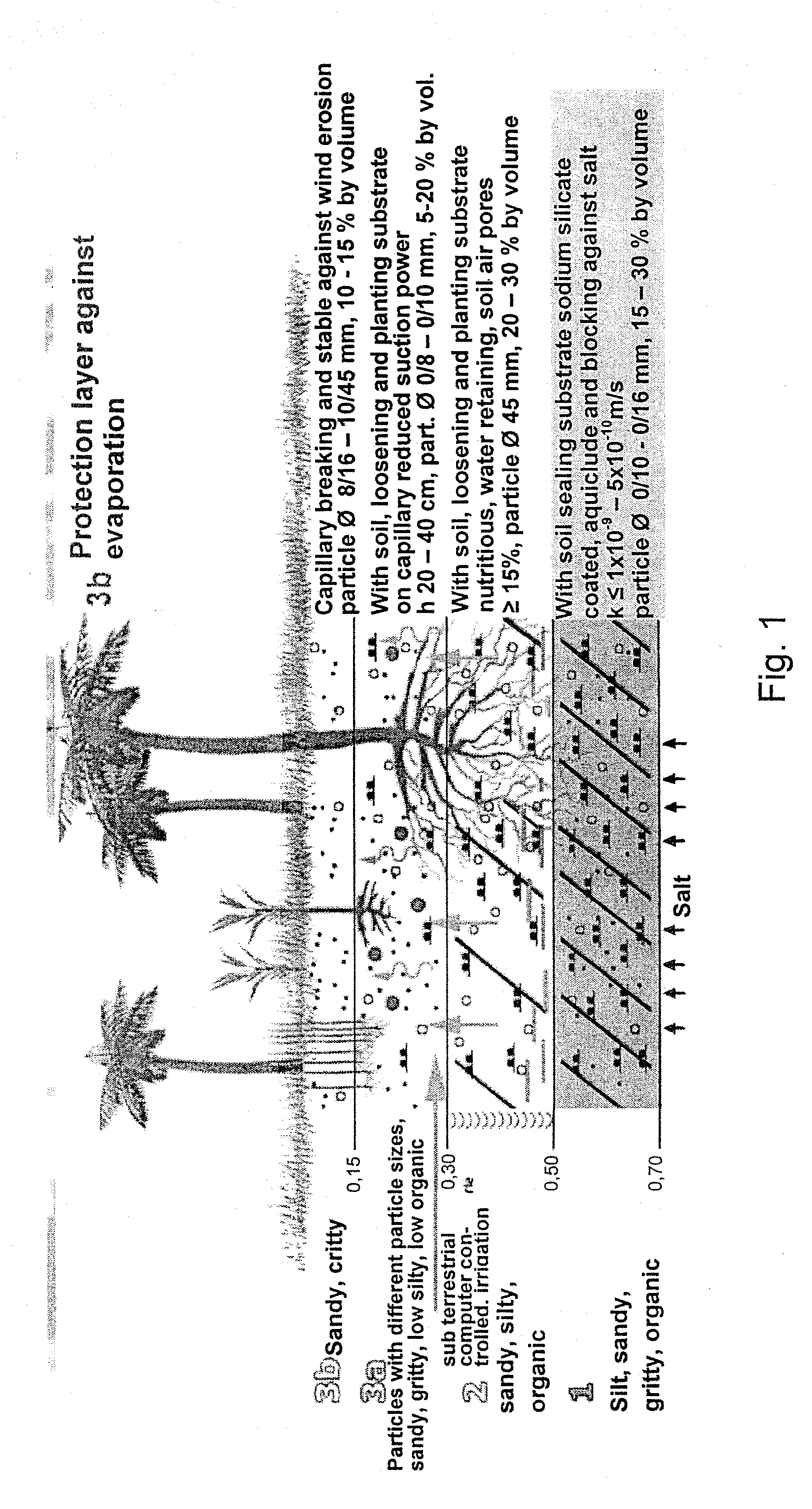
[0024]In the course of the worldwide required climate protection and of the environmental regulations enforce in individual countries that contaminated lands and landfills have to be recultivated. This applies for moderate climatic zones, as for example Central Europe, as well as for arid regions such as South Europe or for large parts in Africa or Asia. In particular, significant efforts have to be done to implement in a big scale in the arid desert regions / steep regions recultivation measures for agricultural plantations, bush planta...


PUM


Abstract

The present invention relates to a method for recycling of synthetic material containing waste. In the process initially in a first step the synthetic material containing waste is crushed to a particle diameter ≦100 mm and then admixed as aggregate in a soil material, in particular in a silt containing soil for the earthworks. The portion of the synthetic material containing waste admixed in the second step is preferably 15 percent by volume to 70 percent by volume. The resulting soil material is in many aspects excellently suited for the earthworks and in particular, for the recultivation or the protection of problematic landfill areas.

Description

1. TECHNICAL FIELD[0001]The present invention relates to a method for recycling of synthetic material containing waste.2. PRIOR ART[0002]Synthetic material containing wastes are a great waste disposal problem. This holds for highly developed societies with well established waste disposal concepts as well as also for developing countries without any infrastructure for the waste disposal.[0003]The usual approach is the incineration of such wastes. However, in this process even in the case of an optimized incineration in a modern plant a very large quantities of CO2 emissions harmful to the climate are generated as is shown by the following estimation: At a usual content of approximately 50% to 70% of TOC (saturated total organic carbon) of the synthetic material containing waste at the oxidation (incineration) the following reaction takes place: C+O2→CO2. Taking into account the atom masses of the involved elements carbon (12) and oxygen (16) this results in a factor of 3.66, i.e. the...

Claims


Application Information

Patent Timeline
IPC IPC(8): B09B3/00B02C23/00
CPCB09B1/004B09B3/00B09C1/00B09C1/08C09K17/16Y02W30/32Y02W30/30
Inventor KUGLER, JOST-ULRICHBELOUSCHEK, PETERKUGLER, KATJA
Owner KUGLER DIPL ING JOST ULRICH
Why Eureka
Try Eureka