
Photovoltaic Module

a photovoltaic module and photovoltaic conversion technology, applied in the direction of pv power plants, semiconductor devices, coatings, etc., can solve the problems of limited efficiency of pv modules laminated with glass, complex manufacturing of glass coverings, and inability to efficiently transmit light in the uv portion of the spectrum, so as to improve weathering and environmental properties, high conversion efficiency, and high optical transparency

Inactive Publication Date: 2009-01-01
ENERIZE CORP
View PDF9 Cites 23 Cited by
  • Summary
  • Abstract
  • Description
  • Claims
  • Application Information

AI Technical Summary

Benefits of technology

[0025]The present invention involves increasing the efficiency of photovoltaic cells or solar cell modules based on mono-crystalline, multi-crystalline, amorphous, and nano-crystalline silicon based systems and for non-silicon systems such as CIGS (copper indium gallium selenide) as well as other cell types.

Problems solved by technology

For example, it is not efficient in transmitting light in the UV portion of the spectrum.
As a result, PV modules laminated with glass have a limited efficiency due to ineffective transmittance in the UV range of the spectrum and due to increased level of reflection from the surface.
Yet another disadvantage of glass coverings complexity of manufacturing cells modules lamination with glass.
The process of lamination of photovoltaic modules includes use of several expensive materials.
Thus the disadvantages of using glass as a covering for photovoltaic cells, as compared to the polymer coating described in the present invention, include: the relatively high cost and weight of glass complexity of assembling the glass-photovoltaic cell unit, the reflectivity of glass and the absorption of energetic photons in the UV portion of the spectrum.
However these structures are expensive and require systems for cleaning and tracking the sun's position.
A further disadvantage of optical concentrators is the fact that they can increase the size and weight of the solar cell module.
Furthermore, polymers described in the prior art do not provide the any increase in the efficiency of the photovoltaic devices on which they are used.

Method used


Image

  • Photovoltaic Module
  • Photovoltaic Module
  • Photovoltaic Module

Examples


example 1

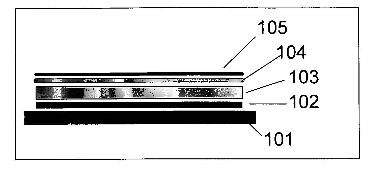
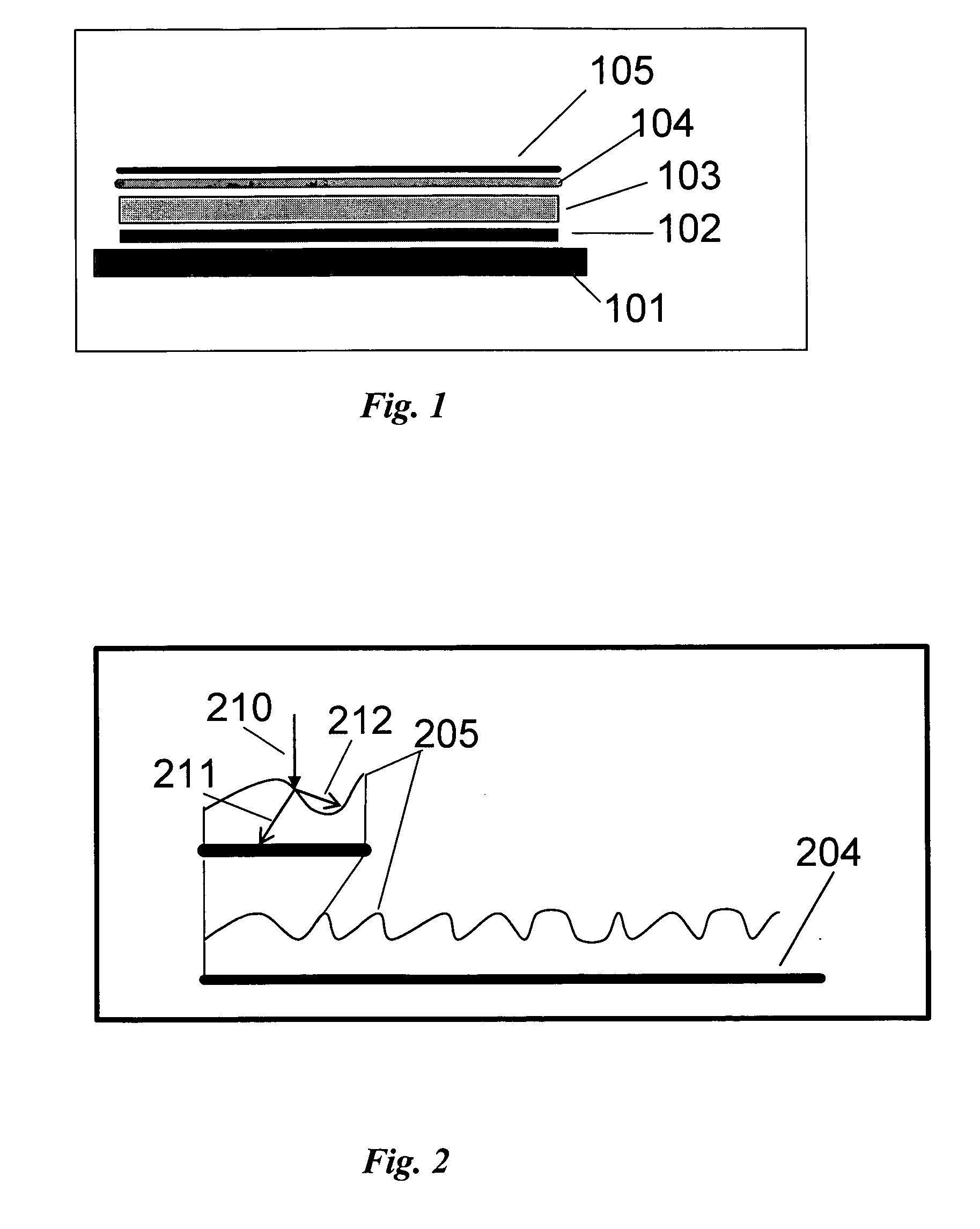
[0060]Three photovoltaic modules were made using the present invention. Aluminum sheeting that was anodized for forming the insulating layer was used as the substrate onto which the back of the photovoltaic converter was affixed.

[0061]The flexible optical transparent cover was made of a modified epoxy-urethane and includes the antistatic additives. The flexible optically transparent cover on the front-face surface of the photovoltaic cell, which was coated with ITO, was made by flowing the initial solution based on epoxy-urethane onto the front-face surface of the photovoltaic cell so as to form the crinkle coat surface morphology.

[0062]Results from tests on the three photovoltaic modules according to the present invention are shown in Table 1 below.

[0063]Modules 5C and 4C consists of solar cells based on the polymer materials and technology according the presented invention. The surface morphology for these modules is flat.

[0064]The front-face surface of the photovoltaic cells was ...

example 2

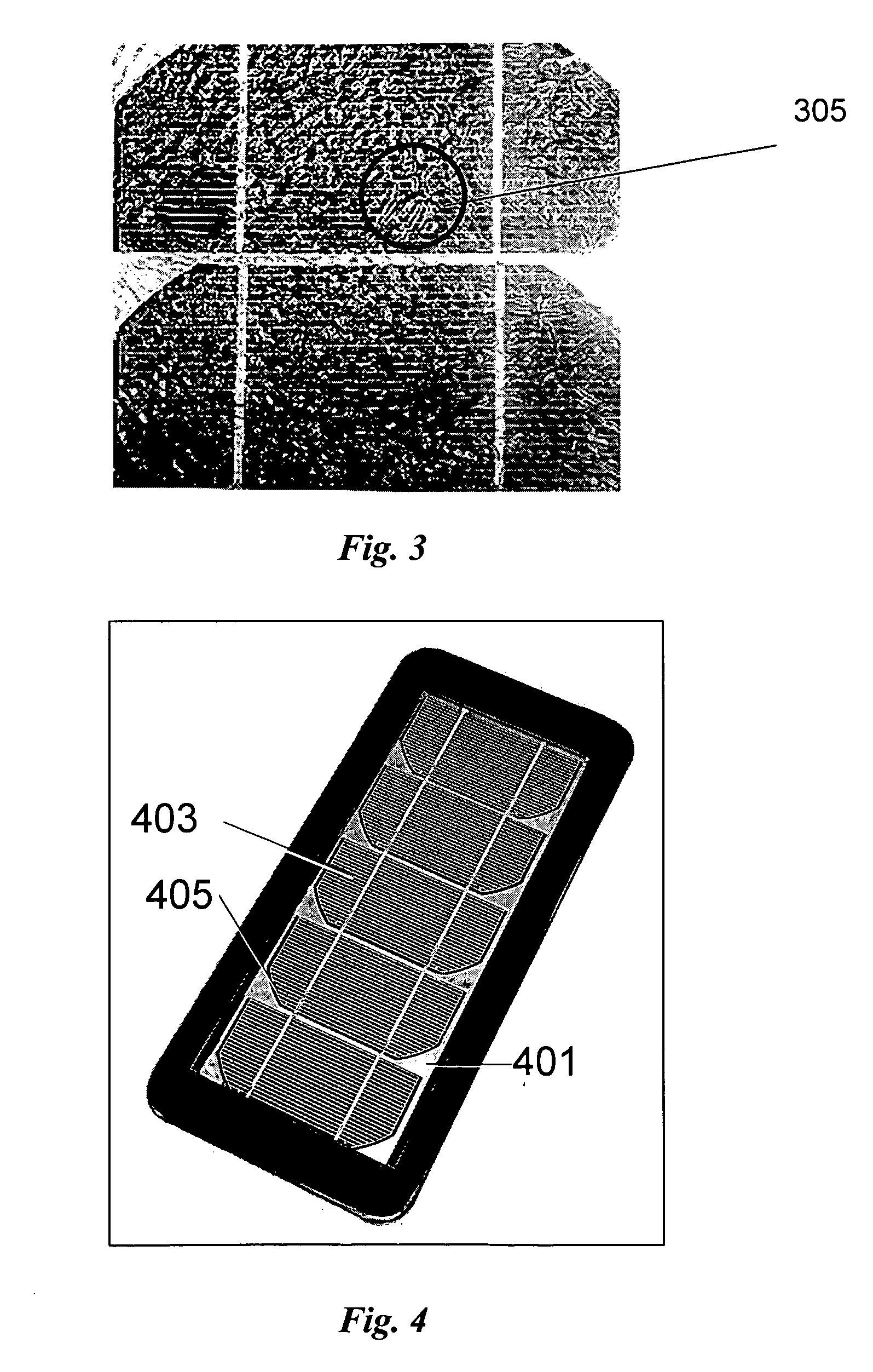
[0067]The SuperPoly module (far right column in Table 1) consists of two solar cells according to the presented invention. The surface for this module is a relief or “crinkle coat” surface morphology. The conditions of the test where the same as for Example 1. The power of the light was 1000 W / m2. The current density for this module under these conditions was 55 mA / cm2. Under these lighting conditions the concentrator effect of the crinkle coat plays a significant role

example 3

[0068]Three photovoltaic modules were made using the present invention.

[0069]The preparing and coating of the polymer film on the light-facing surfaces of the photovoltaic cells was carried out in the following steps:

[0070]1. Preliminary preparing of the oligomer. A mixture of the polyethyleneglycoladipinat with a molecular weight of 800 and the hexamethylendiisocyanate was used.[0071]The mass ratio between the polyethyleneglycoladipinat and hexamethylendiisocyanate was 2:5.4-6.6[0072]The temperature during mixing was 60-70° C.[0073]The duration of mixing was 35-40 minutes

[0074]2. Preparation of the hardener. As a hardener, a mixture of trimethylpropane and butenediol was used. The mass ratio between trimethylpropane and butenediol was 9.5:0.5.

[0075]3. Preparing the mixture of the oligomer and hardener. The mass ratio between oligomer and hardened was 100:3.4-4.5.[0076]The hardener was added to oligomer, which was pre-heated to 55-65° C.[0077]The mixture of the oligomer and hardened...


PUM

PropertyMeasurementUnit
Fractionaaaaaaaaaa
Fractionaaaaaaaaaa
Lengthaaaaaaaaaa

Abstract

The present invention involves the use of specially formulated polymers into which anti-static and conducting metal additives have been incorporated to create a flexible, optically transparent cover for mechanical protection of the incident light-facing surface of the photovoltaic cells. The polymer coating imparts higher conversion efficiencies to photovoltaic cells and modules and is resistant to the destructive effects of UV. In the preferred embodiment, the surface comprising a flexible optically transparent polymer cover has a relief or “crinkle coat” structure morphology comprising a random set of rounded ridge and valley features that impart higher conversion efficiencies to photovoltaic cells and modules due to a concentration affect.Application of the present invention yields mono-crystalline photovoltaic modules that have conversion efficiencies as high as 20%, or more, as compared to 13-14% for presently available commercial module designs. Components of the present invention can be used to increase conversion efficiency of mono-crystalline, multi-crystalline and nano-crystalline, as well as amorphous silicon photovoltaic cells and solar cells based on non-silicon systems such as CIGS (copper indium gallium selenide).

Description

CROSS-REFERENCE TO RELATED APPLICATIONS [0001]Claims priority of Provisional Patent Applications No. 60 / 923,672, Filed Apr. 16, 2007 and No. 60 / 967,490, Filed Sep. 5, 2007.FEDERALLY SPONSORED RESEARCH [0002]NoneSEQUENCE LISTING [0003]NoneFIELD OF THE INVENTION[0004]The present invention relates to the photovoltaic conversion of light and specifically to the use of flexible optically transparent polymer coatings, including metal doped coatings and coatings with antistatic additives, applied directly onto the surface of photovoltaic cells to both protect the semiconductor materials, enhance the overall efficiency of the photovoltaic device.BACKGROUND[0005]Increased photovoltaic cell efficiency and use of lower cost materials are important factors in reducing the cost of solar energy. In addition to the photoelectric conversion efficiency of the specific cells, encapsulation and protective layer material characteristics are important in determining overall photovoltaic device performan...

Claims


Application Information

Patent Timeline
IPC IPC(8): H01L31/042
CPCC08G18/4238C09D175/06H01L31/0547Y02E10/52H01L31/048
Inventor SHEMBEL, ELENA M.SHMYRYEVA, ALEKSANDRATODOSIICHUK, TAMARAKOSYANCHUK, LUDMILAPASTUSHKIN, TYMOFIY V.ALPATOV, ANATOLIYREDKO, VOLODYMYR I.
Owner ENERIZE CORP
Learn More