Biosensor and Biosensor Cell

a biosensor and cell technology, applied in the field of biosensors and biosensor cells, can solve the problems of large and complex devices for maintaining the temperature of incubators, reducing the measurement accuracy of biosensors, and extending the preparation time, so as to achieve easy temperature adjustment of sample solution or the like in the sample chamber, short period of time, and simple structure

Inactive Publication Date: 2009-01-01
NIKKISO COMPANY
View PDF8 Cites 58 Cited by
  • Summary
  • Abstract
  • Description
  • Claims
  • Application Information

AI Technical Summary

Benefits of technology

[0013]According to the biosensor of the present invention, the temperature detection means and the heater member are on top of the supporting layer which is formed as a plate which is capable of miniaturization. As a result, the temperature of the sample solution and the working electrode layer and the like of the biosensor (referred to as the sample solution and the like) is detected by the temperature detection means (thermistor). Based on this temperature detection, temperature adjustment of the sample solution and the like is possible with the heater member. As a result, miniaturization of the biosensor is possible, and in addition, the temperature is always maintained at a constant.
[0014]According to the biosensor cell of the present invention, because it has the biosensor of the present invention, there is no need to use a complex, large temperature adjusting device such as an incubator or the like. Therefore, the biosensor cell

Problems solved by technology

Therefore, when the measurement temperature changes, the measurement values also fluctuate, and as a result, the measurement accuracy of the biosensor is reduced.
As a result, in order for the temperature of the biosensor (measurement temperature) to reach a constant temperature, for example, 30 minutes or greater is needed,

Method used


Image

  • Biosensor and Biosensor Cell
  • Biosensor and Biosensor Cell
  • Biosensor and Biosensor Cell

Examples


embodiment 1

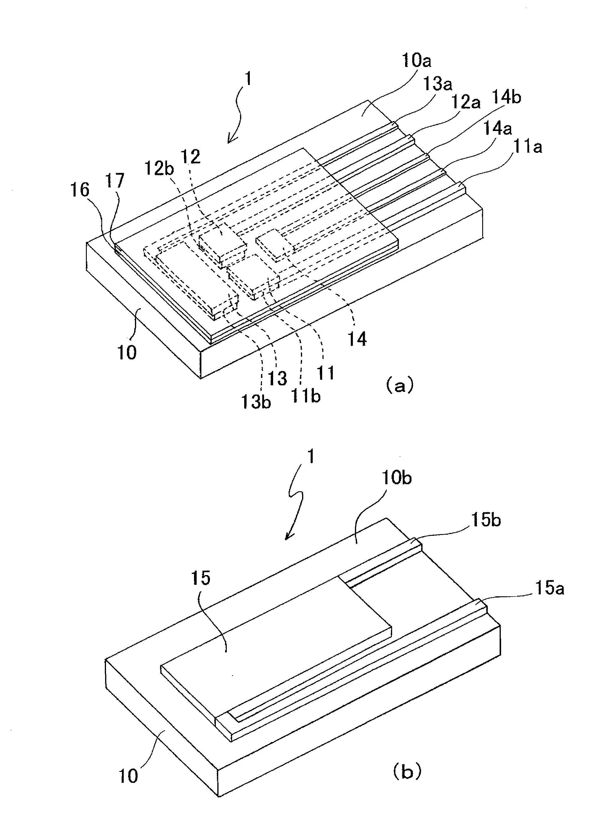
[0088]Polyethylene was molded into a plate of length 40 mm, width 8.5 mm, and thickness 0.5 mm to form the supporting layer 10. Next, in the pattern shown in FIG. 1, the wires 11a, 12a, 13a, 14a, 14b, 15a, and 15b of thickness 10 μm, and ground layers 11b, 12b, and 13b of thickness 10 μm were screen printed onto one surface of the supporting layer 10 using a silver paste with a polyester resin as a base. The width of each wire was 250 μm. The ground layer 11b had a length of 2.5 mm, width of 2.5 mm, and thickness of 10 μm. The ground layer 12b had a length of 0.7 mm, width of 0.7 mm, and thickness of 10 μm. The ground layer 13b had a length of 9.5 mm, width of 2.5 mm, and thickness of 10 μm.

[0089]Next, using a carbon paste with a mixture of a polyurethane resin and vinyl chloride resin as a base, the working electrode layer 12 and the counter electrode layer 13 were formed on top of the ground layers 12b and 13b by screen printing, and the heater member 15 was also formed by screen ...


PUM

PropertyMeasurementUnit
Temperatureaaaaaaaaaa

Abstract

A biosensor includes a supporting layer, a reference electrode layer, a working electrode layer, a counter electrode layer, and a temperature detection device, which are formed on a front surface of the supporting layer, an enzyme film that coats a surface of the working electrode layer, and a heater member formed on a back surface of the supporting layer. A biosensor cell includes a sample chamber to which a sample solution flows in and out, and the above-described biosensor.

Description

CROSS-REFERENCE TO PRIOR APPLICATIONS[0001]The present application is a 371 of International Application No. PCT / JP2006 / 311335, filed Jun. 6, 2006, which claims priority to Japanese Patent Application No. 2005-165275 filed on Jun. 6, 2005, the entire contents of which being hereby incorporated herein by reference.FIELD OF THE INVENTION[0002]The present invention relates to a biosensor and a biosensor cell. Described in more detail, the present invention relates to a biosensor which forms a small biosensor cell with good temperature stability. The present invention also relates to a small biosensor cell which has good temperature stability.BACKGROUND OF THE INVENTION[0003]A biosensor is a sensor which uses a biological material or a biologically derived material (referred to as biological material and the like) as a molecular recognition element. For example, enzyme sensors and the like which use enzymes as the biological materials and the like are known. The biosensor is used to mea...

Claims


Application Information

Patent Timeline
IPC IPC(8): G01N27/28
CPCG01N27/3272C12Q1/001
Inventor AKAHORI, YUKIHIROYAMAZAKI, HIROMI
Owner NIKKISO COMPANY
Why Eureka
Try Eureka