Process for the production of polyurethane molded articles

a polyurethane and molded article technology, applied in the direction of superstructure subunits, layered products, construction elements, etc., can solve the problems of poor edge definition of three-dimensional parts, insufficient material infilling, general unsatisfactory edge definition, etc., and achieve good edge definition

Inactive Publication Date: 2009-01-01
BAYER MATERIALSCIENCE AG
View PDF7 Cites 3 Cited by
  • Summary
  • Abstract
  • Description
  • Claims
  • Application Information

AI Technical Summary

Benefits of technology

[0005]The object of the present invention is to provide a process that enables three-dimensional PU articles with good edge definition to be produced in a simple way.

Problems solved by technology

The previous processes for the production of PU molded articles, in particular PU sandwich structural parts, provide three-dimensional parts with a poor edge definition and / or insufficient material infilling.
Especially in the case of highly contoured articles, the edge definition is generally unsatisfactory.
In addition, the amount of polyurethane that can be applied is restricted, since the applied liquid polyurethane mixture tends to drip.

Method used


Image

  • Process for the production of polyurethane molded articles
  • Process for the production of polyurethane molded articles
  • Process for the production of polyurethane molded articles

Examples


example 1

According to the Invention

[0039]The A Component of Formulation 1 was charged with gaseous CO2 using a star-shaped type hollow-shaft stirrer. After charging, a polyol density of 420 kg / m3 was measured by liter gauging.

[0040]Chopped glass fiber were applied in an area weight of 450 g / m2 to both sides of a core layer consisting of a paper honeycomb of corrugated cardboard 5 / 5 type 10 mm thick and spray-coated at room temperature with a total of 450 g / m2 of the polyurethane Formulation 1 charged with CO2.

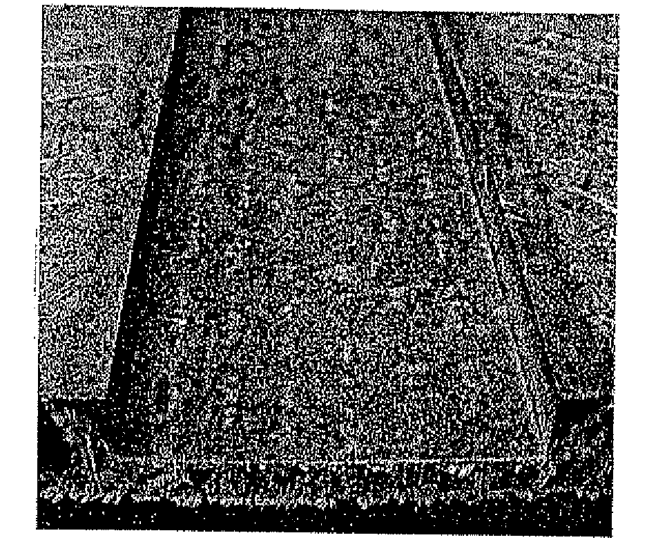
[0041]This sandwich was placed in a sheet-forming mold, into which a sharp-edged flat piece of steel of size 6×30×300 mm had previously been inserted for the shaping. The sandwich was then compressed to a wall thickness of 9.8 mm, in the mold heated to 130° C., the sandwich having been more strongly compressed to a wall thickness of 3.8 mm in the region of the flat steel insert.

[0042]The more strongly compressed region had a sharp edge definition, as shown in FIG. 1.

example 2

Comparison

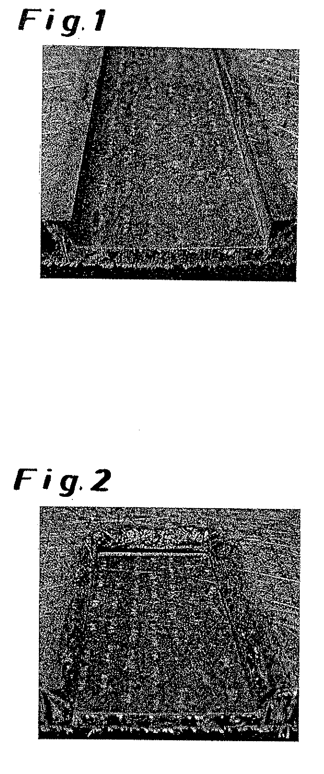
[0043]The experiment described in Example 1 was repeated, except that the Formulation was not charged with CO2.

[0044]The more strongly compressed region had a defective edge definition, as shown in FIG. 2.

example 3

According to the Invention

[0045]The polyurethane-forming Formulation 1 was charged as in Example 1 with gaseous CO2.

[0046]Chopped glass fibers were applied in an area weight of 450 g / m2 to both sides of a core layer consisting of a paper honeycomb of corrugated cardboard 5 / 5 type 40 mm thick and spray-coated at room temperature with 550 g / m2 of the polyurethane Formulation 1 charged with CO2. In addition, during the spraying, chopped glass fibers of the type 816, 2400 tex / Mühlmeier, were applied by means of a cutter, type SW 2 / Wolfangel, in the region of the subsequent shaping.

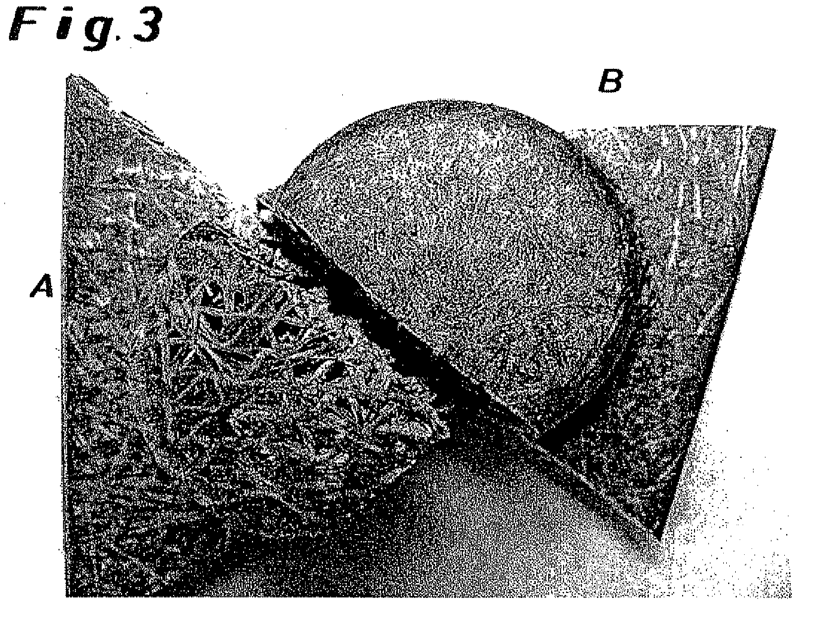
[0047]This sandwich was placed in a sheet-forming mold, that permitted the formation of a 35 mm high, cylindrical dome of 50 mm diameter through a corresponding depression in the upper part of the mold. The sandwich was then compressed to a wall thickness of 17 mm in the mold heated to 130° C., the region of the dome being correspondingly less markedly compressed.

[0048]The dome that was formed had the closed s...


PUM

PropertyMeasurementUnit
temperatureaaaaaaaaaa
mold temperatureaaaaaaaaaa

Abstract

The present invention relates to a process for the production of polyurethane molded articles in which the polyurethane-forming mixture applied to reinforcing fiber layer(s) or a reinforcing fiber mat includes a gas and a foam stabilizer. These molded articles are useful in automotive and construction applications and in furniture.

Description

BACKGROUND OF THE INVENTION[0001]The present invention relates to a process for the production of polyurethane (PU) molded articles, in particular PU sandwich structural parts, and their use.[0002]Processes for the production of sandwich elements for the fabrication of flat sheets have been known for some time. The sandwich construction is made up of a light and compression-resistant core with high-strength covering layers. This composite structure is formed by a PU reaction mixture which, when applied on both sides in a thermal compression molding process, can form an indissoluble bond. The inner core layer of the sandwich structure is preferably made up of cardboard with a honeycomb structure, which during the compression procedure acts as a spacer for the covering layers wetted with PU. The wetting of the sandwich covering layers is preferably effected by spraying. The substrate carrier is in this case robot-guided, and during the PU application by means of a mixing head is arran...

Claims


Application Information

Patent Timeline
Patent Type & Authority Applications(United States)
IPC IPC(8): B29C65/02B29C44/12B29C44/14B29C70/08B29C70/28B32B5/22B32B27/04B32B27/12B60R13/02C08G18/48C08J5/00C08J5/04
CPCB29C44/1209B29C70/086C08G2101/0008B32B5/22C08G18/4812B29C70/088C08G2110/0008B29C43/00B29C44/12B29C44/16B32B27/12B32B27/18B32B27/40B32B2250/40B32B2266/00B32B2305/28B32B2309/02B32B2310/04B32B2375/00B32B2419/00B32B2605/08
Inventor WIRTZ, HANS-GUIDOSYMANNEK, ACHIMPAUL, REINERWEGENER, DIRK
Owner BAYER MATERIALSCIENCE AG
Why Eureka
Try Eureka