
Saw sensor with adjustable preload

a preload sensor and adjustable technology, applied in the field ofsaw sensors, can solve the problems of large package lid thickness, difficult mechanical preloading of the sensor, and inability to use laser trimming anymor

Inactive Publication Date: 2009-01-01
TRANSENSE TECH
View PDF6 Cites 13 Cited by
  • Summary
  • Abstract
  • Description
  • Claims
  • Application Information

AI Technical Summary

Benefits of technology

[0007]The aim of the present invention is therefore to provide a simplified system for setting the preload of a SAW sensor which overcomes the problems of the prior art. A further aim is to provide a package for a SAW pressure sensing die that will allow the sensor to work at high pressure and simplify the assembly procedure and thus reduce the sensor cost.
[0009]A SAW based sensor in accordance with the invention has the advantage that the provision of a thread coupling between the lid and the base enables separation of the lid relative to the base, and hence load applied to the substrate by the projection, to be adjusted and set very easily by simply screwing the lid onto or off of the base or vice versa. Once the desired preload is achieved, the lid and base can then be permanently secured together, for example by means of a thread-lock adhesive, welding or the like so as to prevent accidental relative rotation between the two parts.
[0012]Preferably the lid is a cylindrical cap having a female thread formed on its inner cylindrical surface which engages with a complementary male thread formed on an outer circumferential surface of the base. The engagement between the lid and the base, will, of course, form a hermetic seal such that the cavity can be maintained at a different pressure to the surrounds, thereby enabling monitoring of pressure.
[0014]The configuration is particularly applicable for use in measuring high pressure. The thickness and the diameter of the diaphragm can be selected / adjusted to control the flexibility of the diaphragm so that the maximum pressure to which the diaphragm is exposed does not result in an amount of strain in the SAW substrate being induced which would cause the resulting frequency shift to exceed the value limited by the ISM band width.
[0016]Preferably the closed end of the base is thinner in a central region which overlies the blind bore and acts as a diaphragm than the region which surrounds the central region. This ensures that a robust region is provided for carrying the thread which mates with the lid whilst the diaphragm responsiveness can be set to meet the required. Moreover, the thicker outer section will be less susceptible to deformation during heating, enabling welding to be used to permanently fix the lid to the base without requiring subsequent tuning / trimming.

Problems solved by technology

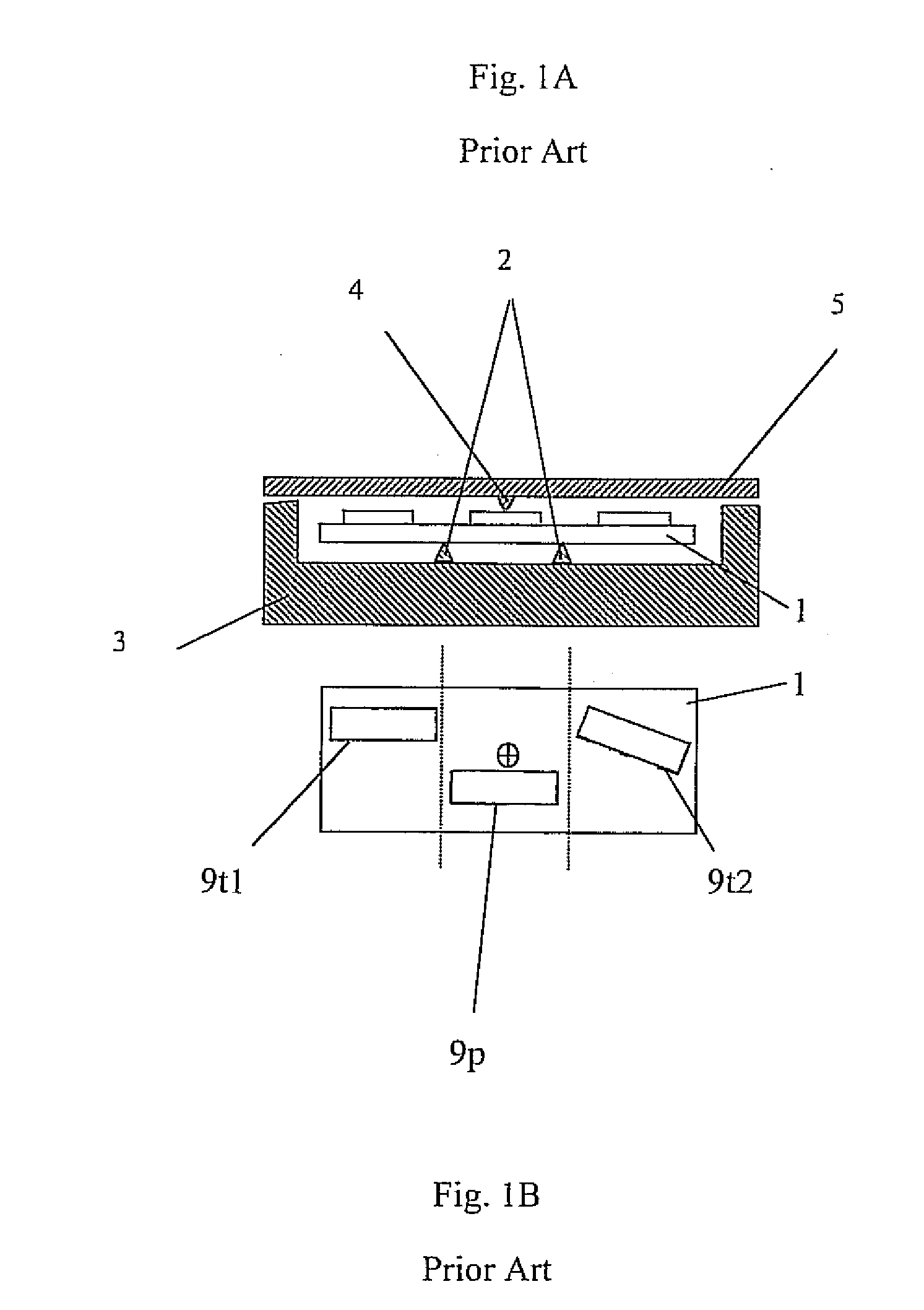
However, if the pressure to be measured is as high as 3000-5000 psi, the lid thickness of the package shown in FIG. 1 becomes so large that the laser trimming cannot be used any more.
Mechanical preloading of the sensor becomes very difficult.

Method used


Image

  • Saw sensor with adjustable preload
  • Saw sensor with adjustable preload
  • Saw sensor with adjustable preload

Examples


Embodiment Construction

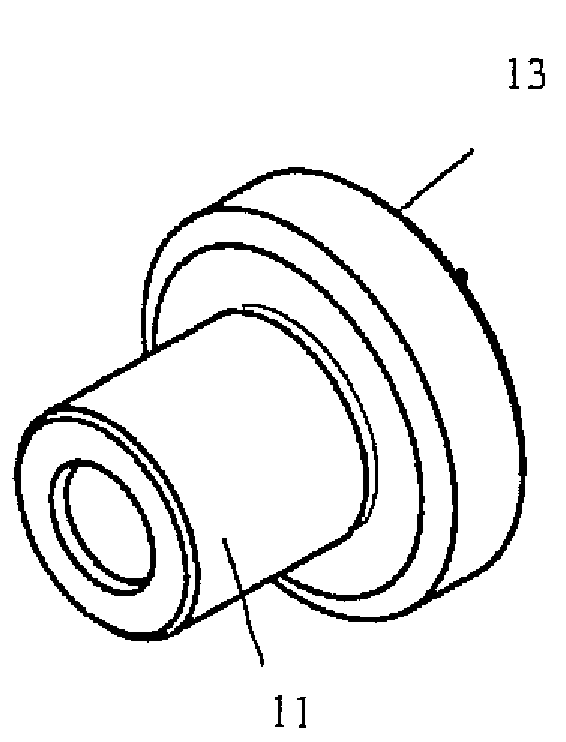
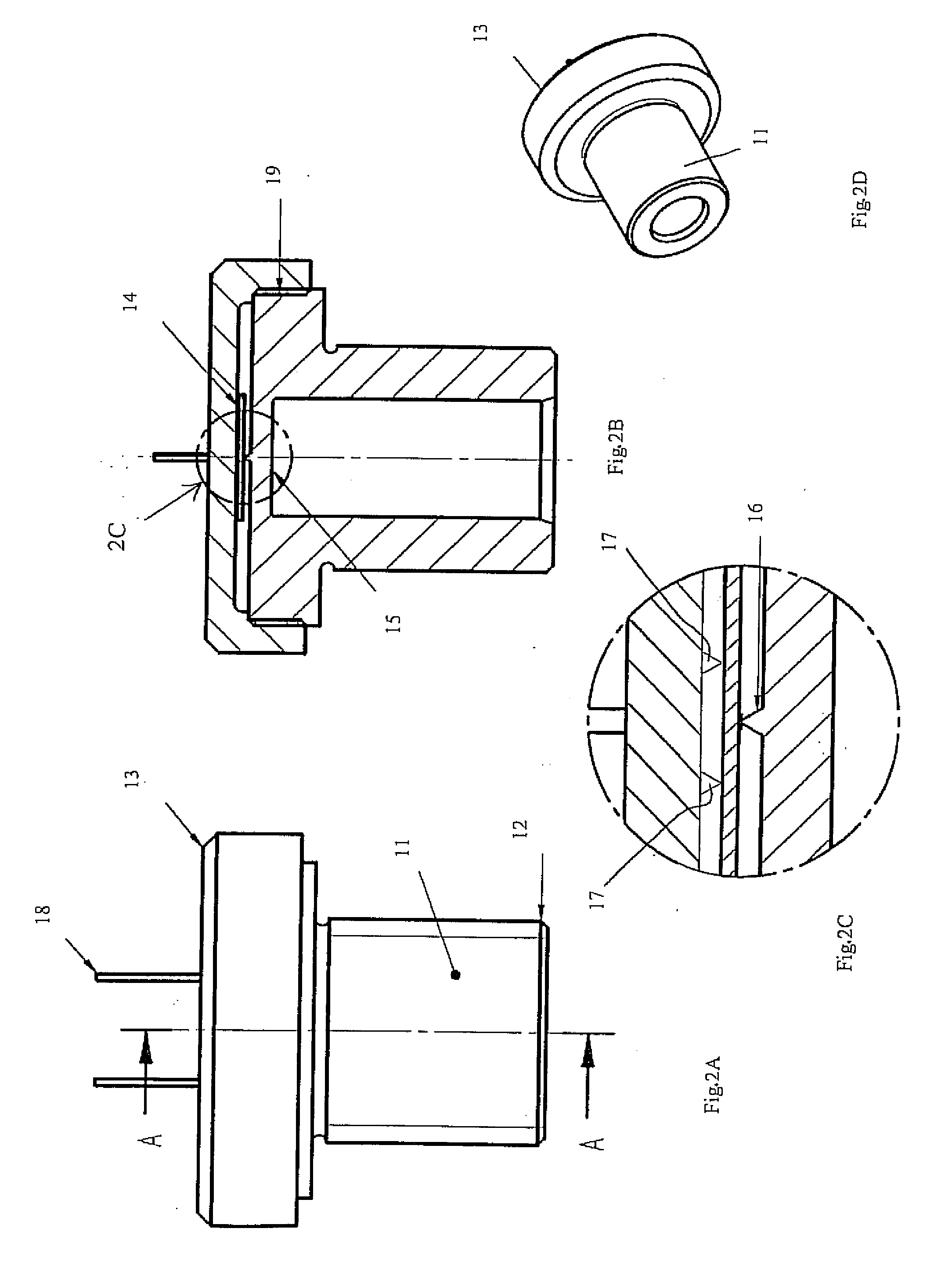
[0024]To facilitate mechanical preloading of the existing SAW sensing die, and simplify application of high pressure to the sensor, a new package is proposed according to the present invention as shown in FIGS. 2A, 2B, 2C and 2D. The package consists of two cylindrical parts, a base 11 with a thread 12 and a tubular hole, and a lid 13. The thread 12 is used to screw the sensor into a high-pressure pipeline or a tank so that the high pressure acts upon the diaphragm 15 formed in the base 11. Base 11 and lid 13 cooperatively form a substrate-receiving cavity therebetween. The SAW sensing die 14 is attached to the two ledges 17 formed on the inner surface of the lid 13. The ledges face towards the base, and are symmetrically located on either side of the center of the lid and extend parallel to each other. A projection, preferably formed as a dimple, is disposed in the center of the base. In an alternate embodiment, the ledges are formed on the base and the dimple is formed on the lid....


PUM


Abstract

A SAW based sensor having a base and a lid engageable with the base to form an internal cavity therewith. A substrate is supported in the cavity on either tile base or the lid 13 and a dimple 16 is formed on the other which extends towards the substrate so as to engage against the substrate and apply a preload thereto. The base and lid include complementary threads by means of which they are attachable to each other. The preload applied to the substrate by the dimple 16 is adjustable by varying the rotational position of the lid relative to the base.

Description

BACKGROUND OF THE INVENTION[0001]1. Field of the Invention[0002]The present invention relates to SAW sensors having an adjustment for setting the preload, and more particularly to SAW pressure sensors including passive wireless SAW pressure sensors that can be used to measure high pressures[0003]2. The Prior Art[0004]SAW pressure sensors are very well known in practice. They are based either on delay lines or on resonators. They can be either wired or wireless passive devices. In the former case they can be a part of an oscillator feedback loop so the frequency of the (Continuous Wave) CW signal generated by the oscillator will depend on pressure. In the latter case they can be connected to an antenna forming a passive backscatterer. Interrogation of such a passive wireless sensor can be performed by a short RF pulse. The signal reflected from the sensor antenna will carry the information on the phase delays of the SAW (in the case of a reflective delay line sensor) or on the freque...

Claims


Application Information

Patent Timeline
Patent Type & Authority Applications(United States)
IPC IPC(8): H01L41/113H10N30/30
CPCG01L1/165G01D11/245G01L19/14G01L9/0025
Inventor KALININ, VICTOR ALEXANDROVICHLOHR, RAYMOND DAVIDLEIGH, ARTHUR JOHN
Owner TRANSENSE TECH
Learn More