Charging apparatus and image forming apparatus

Inactive Publication Date: 2009-01-01
SHARP KK
View PDF6 Cites 10 Cited by
  • Summary
  • Abstract
  • Description
  • Claims
  • Application Information

AI Technical Summary

Benefits of technology

[0018]Accordingly, it is an object of the invention to provide a charging apparatus which is excellent in charging uniformity and thus allows a to-be-charged body to be charged uniformly and in which the generation of discharge products can be reduced, and an image forming apparatus provided with the charging apparatus.

Problems solved by technology

However, the corona discharge-type charging apparatuses disclosed in JP-A 6-11946, JP-A 10-274892, and JP-A 2004-69860 described supra present a plurality of problems.
The first problem resides in a space for placing the charging apparatus.
For that, there is not sufficient space for the placement of the charging apparatus.
This makes difficult the layout of the corona discharge-type charging apparatus which occupies a relatively large space.
The second problem resides in a discharge product which is formed when the to-be-charged body 11 is charged by the charging apparatus.
If ozone is produced in large quantity in that way, various problems will arise such as occurrence of ozone odor, detrimental effects on the human body, and quality degradation in components induced by significant oxidative power.
On the other hand, if oxides of nitrogen are produced, a defective image will be caused, because the oxides of nitrogen are adhered to the photoreceptor as ammonium salt (ammonium nitrate).
The third problem resides in a corona wind which is generated when the to-be-charged body 11 is charged by the charging apparatus.
In this contact charging-type charging apparatus, however, since the to-be-charged body is charged through the contact with the conductive roller or conductive brush, it is difficult to achieve the charging without distorting a toner image formed on the to-be-charged body.
Therefore, the use of the contact charging-type charging apparatus as a before-transfer charging apparatus will be inappropriate.
That is, the effect of reducing discharge product generation is not good enough.
Furthermore, in the charging apparatus disclosed in JP-A 8-160711, the gap between the discharge electrode and the grid electrode is so small that discharge products, as well as foreign matters such as toner and powdery paper originating from a recording sheet which is a material subjected to transfer, are prone to adhere to the discharge electrode.
The removal (cleaning) of such a foreign matter adhered to the discharge electrode is difficult to achieve, because the discharge surface of the discharge electrode in the corona discharge system is given a complicated configuration, such as an acicular shape.
In addition, the front end of the discharge electrode is susceptible to abrasion and quality degradation due to discharge energy, which results in lack of stability in the discharging effected by the discharge electrode.
Although it may be possible to reduce the pitch of arrangement of the discharge electrodes to eliminate the charging variation, the reduction of pitch leads to an increased number of discharge electrodes and thus to increased manufacturing costs.
This makes it difficult for the to-be-charged body to be charged uniformly.
This leads to poor ion-use efficiency.
However, the increase of the applied voltage or frequency requires a measurable amount of electric power and also causes a decrease in the service lifespan of the discharge electrode.

Method used


Image

  • Charging apparatus and image forming apparatus
  • Charging apparatus and image forming apparatus
  • Charging apparatus and image forming apparatus

Examples


first embodiment

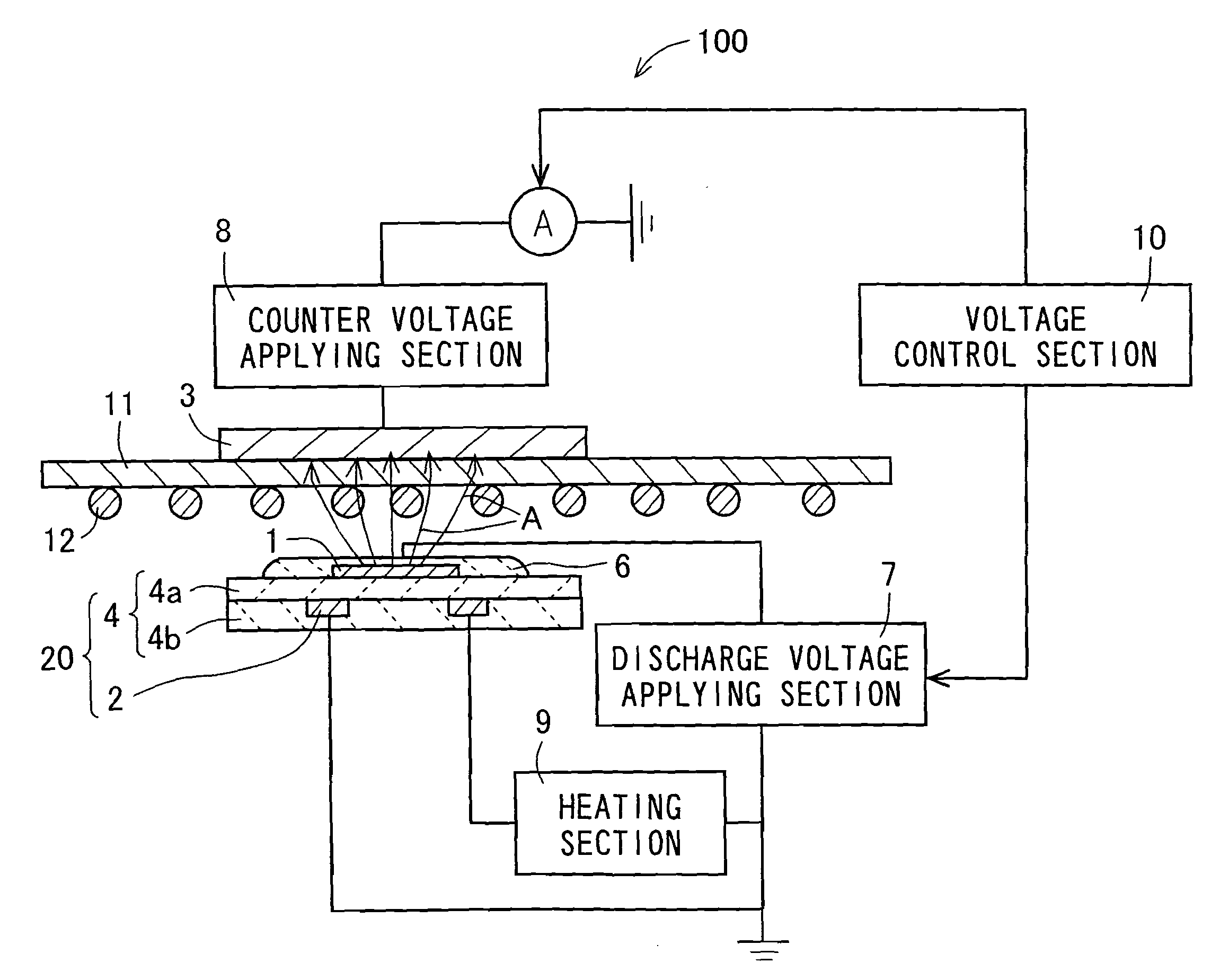
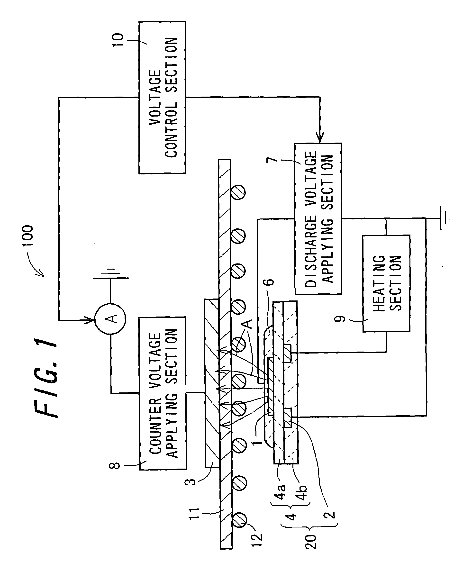
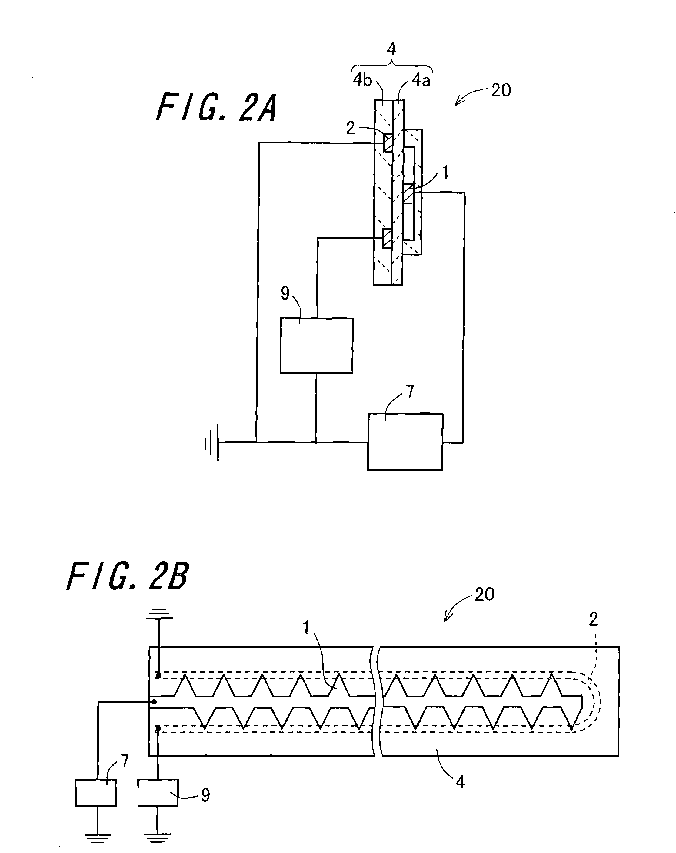
[0128]FIG. 1 is a view showing the constitution of a charging apparatus 100 in accordance with the invention. Moreover, FIGS. 2A and 2B are views showing the structure of an ion generating section 20. The charging apparatus 100 performs charging on a target object to be charged, namely a to-be-charged body 11. In a case where a toner image is formed on the to-be-charged body 11, toner 12 existing on the to-be-charged body 11 is subjected to charging. The charging apparatus 100 is composed of the ion generating section 20, a counter electrode 3, and a voltage control section 10.

[0129]The ion generating section 20 is a component to generate an ion for charging the to-be-charged body 11, and is composed of a dielectric body 4, a discharge electrode 1, an induction electrode 2, and a protective layer 6. The dielectric body 4 is constructed of a flat plate formed by bonding substantially rectangular-shaped upper and lower dielectrics 4a and 4b together. As a material for forming the diel...

second embodiment

[0143]FIG. 3A is a view showing the constitution of an image forming apparatus 200 in accordance with the invention. The image forming apparatus 200 is of a so-called tandem type and is also built as a printer that employs an intermediate transfer system to form a full-color image. The image forming apparatus 260 includes: a photoreceptor 31; a developing section 32; a transfer section 40; a fixing section 50; a photoreceptor cleaning section 33; a before-latent image-formation charging section 110; a before-intermediate-transfer charging section 120 acting as a first charging section; and a before-recording-transfer charging section 130 acting as a second charging section.

[0144]In order to deal with image data on different colors: cyan (C); magenta (M); yellow (Y); and black (K) included in color image data on an individual basis, the photoreceptor 31, a laser writing section (not shown in the figure), the developing section 32, the transfer section 40, the photoreceptor cleaning s...

third embodiment

[0158]FIG. 3B is a view showing the constitution of an image forming apparatus 210 in accordance with the invention. The image forming apparatus 210 is made the same as the image forming apparatus 200, except that, in the former, there is disposed a before-cleaning charging section 140 between the transfer section 40 and the photoreceptor cleaning section 33. The before-cleaning charging section 140, which acts as a third charging section, is constituted by the above-described charging apparatus 100. Herein, such constituent components as are common to those in the image forming apparatus 200 will be denoted by the same reference numerals and symbols, and overlapping descriptions will be omitted.

[0159]The before-cleaning charging section 140 is a component to charge toner left untransferred after the photoreceptor 31-transfer belt 41 transfer process, namely residual toner. In the before-cleaning charging section 140, a target object to be charged, namely a to-be-charged body is the...


PUM


Abstract

A charging apparatus which is excellent in charging uniformity and thus allows a to-be-charged body to be charged uniformly and in which the generation of discharge products can be reduced, is provided. In the charging apparatus, ions are generated under the difference in electrical potential between the discharge electrode and the induction electrode produced in the ion generating section. The generated ions are caused to flow toward the counter electrode, whereupon the to-be-charged body arranged between the ion generating section and the counter electrode is charged.

Description

CROSS-REFERENCE TO RELATED APPLICATION[0001]This application claims priority to Japanese Patent Application No. 2007-171161, which was filed on Jun. 28, 2007, the contents of which are incorporated herein by reference in its entirety.BACKGROUND OF THE INVENTION[0002]1. Field of the Invention[0003]The present invention relates to a charging apparatus and an image forming apparatus having the charging apparatus.[0004]2. Description of the Related Art[0005]In an image forming apparatus which employs an electrophotographic method, a charging apparatus of a corona discharge type is used for its charging section which uniformly charges a photoreceptor, namely an image bearing member which bears an electrostatic latent image thereon, transfer section which transfers a toner image formed on the photoreceptor onto a recording sheet, which is a material subjected to transfer and a recording medium as well, via a transfer belt which is a member subjected to transfer and an intermediate transfe...

Claims


Application Information

Patent Timeline
IPC IPC(8): G03G15/02
CPCG03G15/0291G03G2215/02
Inventor KAGAWA, TOSHIAKIDOSHOHDA, HIROSHIADACHI, KATSUMI
Owner SHARP KK
Why Eureka
Try Eureka