Method and apparatus for measuring current density in conductive materials

Inactive Publication Date: 2009-01-01
RGT UNIV OF CALIFORNIA
View PDF6 Cites 14 Cited by
  • Summary
  • Abstract
  • Description
  • Claims
  • Application Information

AI Technical Summary

Benefits of technology

[0006]The present invention provides an apparatus and method for measuring a current density in a conductive material. The apparatus and method use an algorithm and an extension to the Fourier transform approach

Problems solved by technology

All of these approaches have disadvantages of being incommensurate with transport current, tending to diverge in some situations, or having limited speed.
Current methods of determining the current dens

Method used


Image

  • Method and apparatus for measuring current density in conductive materials
  • Method and apparatus for measuring current density in conductive materials
  • Method and apparatus for measuring current density in conductive materials

Examples


example 1

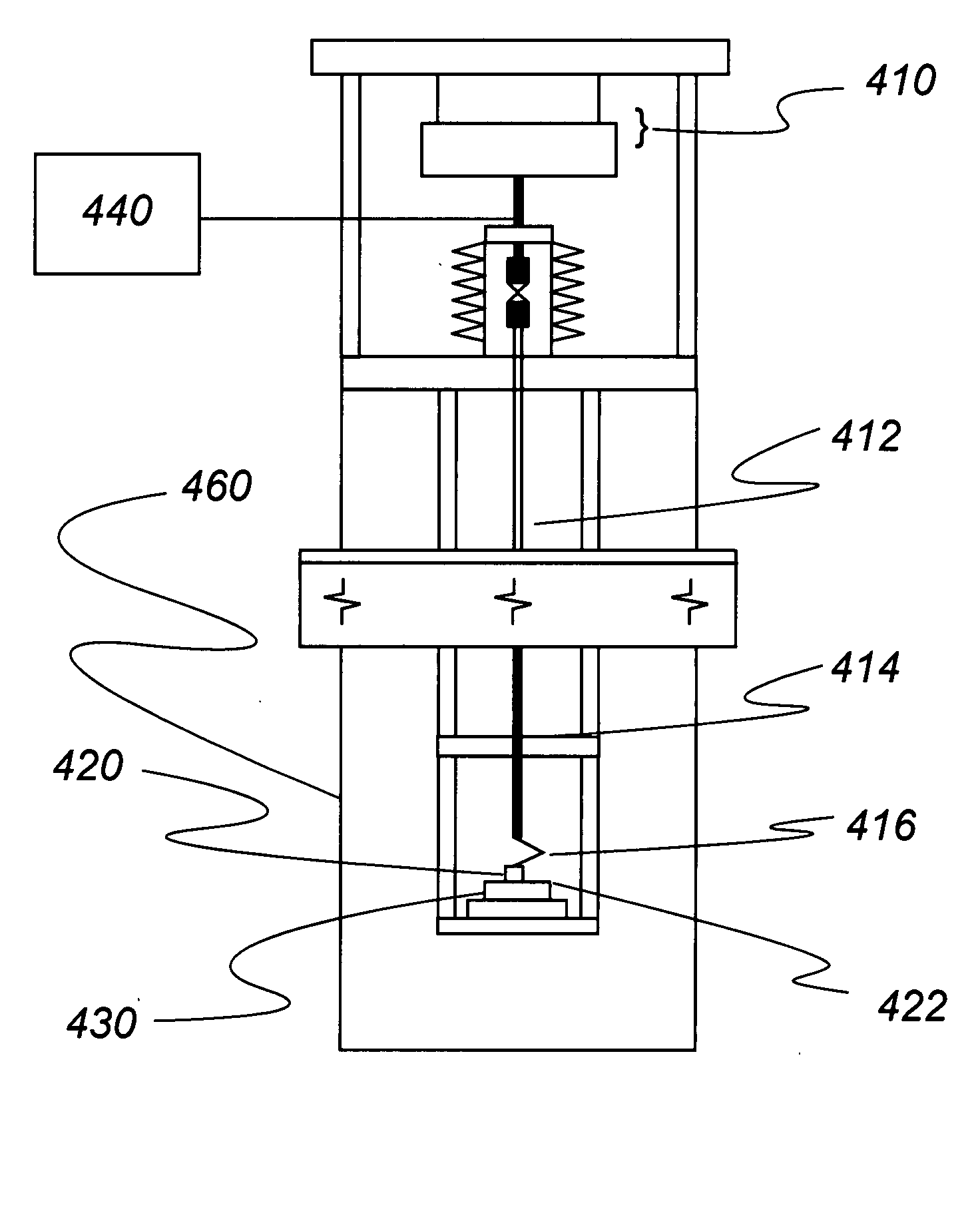
[0031]Current densities for conductive YBCO tapes were obtained using the imaging apparatus described herein and shown in FIG. 4. The conductive YBCO tapes consist of a 100 micrometer thick nickel alloy substrate, a textured ceramic buffer layer deposited using an ion beam assisted deposition (IBAD) technique, a high-temperature superconducting (HTS) layer, and a 3 micrometer thick protective silver overlayer. The HTS layer was fabricated by metal organic vapor deposition (MOCVD) and pulsed laser deposition (PLD). The thickness of each of the buffer and HTS layers was in the range of 1-2 micrometers.

[0032]A magnetoresistive sensor was scanned a small height h above the superconducting tape sample. The sensor generated an output signal based on the component bZ of the magnetic field perpendicular to the plane of the tape. The sensor signal was recorded on an equispaced grid spanning a travel of twice the tape width in both the x (along the tape) and y (across the tape) directions. Th...


PUM


Abstract

The present invention relates to an apparatus and method for measuring a current density in a conductive material. The apparatus and method use an algorithm and an extension to the Fourier transform approach that allows transport currents to be treated accurately. Due to its speed, the resulting algorithm is ideally suited for high-resolution and high-throughput magnetic imaging of superconducting tape in real time.

Description

STATEMENT REGARDING FEDERAL RIGHTS[0001]This invention was made with government support under Contract No. DE-AC52-06NA25396, awarded by the U.S. Department of Energy. The government has certain rights in the invention.BACKGROUND OF INVENTION[0002]The invention relates to measuring the current density of a conductor. More particularly, the invention relates to a method and apparatus for measuring the current density within a conductor; Even more particularly, the invention relates to a method and apparatus for measuring the current density within a conductor using an inversion algorithm.[0003]Superconducting coated conductor tapes can replace conventional conductors in electrical power applications such as transformers, motors, and generators to improve energy efficiency and reduce size. High and consistent current carrying capability is the prime target for coated conductor manufacturing.[0004]Electric currents flowing in a conductor generate magnetic fields in the surrounding spac...

Claims


Application Information

Patent Timeline
IPC IPC(8): G01R19/08G01R33/09
CPCG01R15/20G01R33/09G01R19/08
Inventor MUELLER, FREDERICK M.GRUBE, HOLGERBROWN, GEOFFREY W.HAWLEY, MARILYN E.COULTER, J. YATES
Owner RGT UNIV OF CALIFORNIA
Why Eureka
Try Eureka