Longitudinal quantum heat converter

a long-range, quantum heat converter technology, applied in the manufacture/treatment of thermoelectric devices, semiconductor lasers, thermoelectric devices, etc., can solve the problems of large installation requirements of all these energies, low efficiency of this method, and low amount of energy produced

Inactive Publication Date: 2009-01-08
STEFANESCU ELIADE +1
View PDF17 Cites 9 Cited by
  • Summary
  • Abstract
  • Description
  • Claims
  • Application Information

AI Technical Summary

Benefits of technology

[0013]According to an advantageous variant, the n-i-p-n structure with quantum dots forms a super radiant transistor, the p-region being much narrower than the electron diffusion length, thus enabling the diffusion of these electrons from the n-i emitter region mainly to the collector p-n internal field region.
[0014]According to an advantageous variant, the first n and the p regions of the n-i-p-n structure form two conduction regions, and quantum dots together with the i-layer form an active quantum dot region which is separated from the two conduction regions by potential barriers, to diminish the dissipative coupling of the active electrons with the electrons in the conduction regions.
[0015]According to an advantageous variant, the potential barriers have rather high penetrability to enable quantum tunnelling between the active quantum dot region and the conduction regions.
[0016]According to an advantageous variant, the active cavity comprises several n-i-p-n structures connected in series so that there is an accumulation of super radiant transitions. Furthermore, such series of longitudinal quantum heat converters have the advantage of presenting an increased absorption power of the environmental heat.

Problems solved by technology

Nevertheless, all these energies require huge installations such as fields of solar panels or wind turbines or hydroelectric power stations and long distribution networks.
Furthermore, the amount of energy produced is very low in comparison to the efforts and means needed.
However, the efficiency of this method is rather low, especially for three main reasons: (1) only a narrow part of the incident radiation spectrum is converted into energy, this conversion being based on a quasi-resonant effect of transitions between the margins of the conduction bands stimulated by light, (2) the efficient absorption region, that is restricted to the internal field zone of a semiconductor junction, is rather narrow, an important part of the incident field being lost in the neighbouring neutral zones of the device that do not produce any conversion of radiation into electric power, and (3) the excited charges, electrons and holes coexisting in the same semiconductor region, have large wave-function overlaps, leading to strong dissipative couplings between the charge carriers, and between these carriers and the crystal lattice.

Method used


Image

  • Longitudinal quantum heat converter
  • Longitudinal quantum heat converter
  • Longitudinal quantum heat converter

Examples


Embodiment Construction

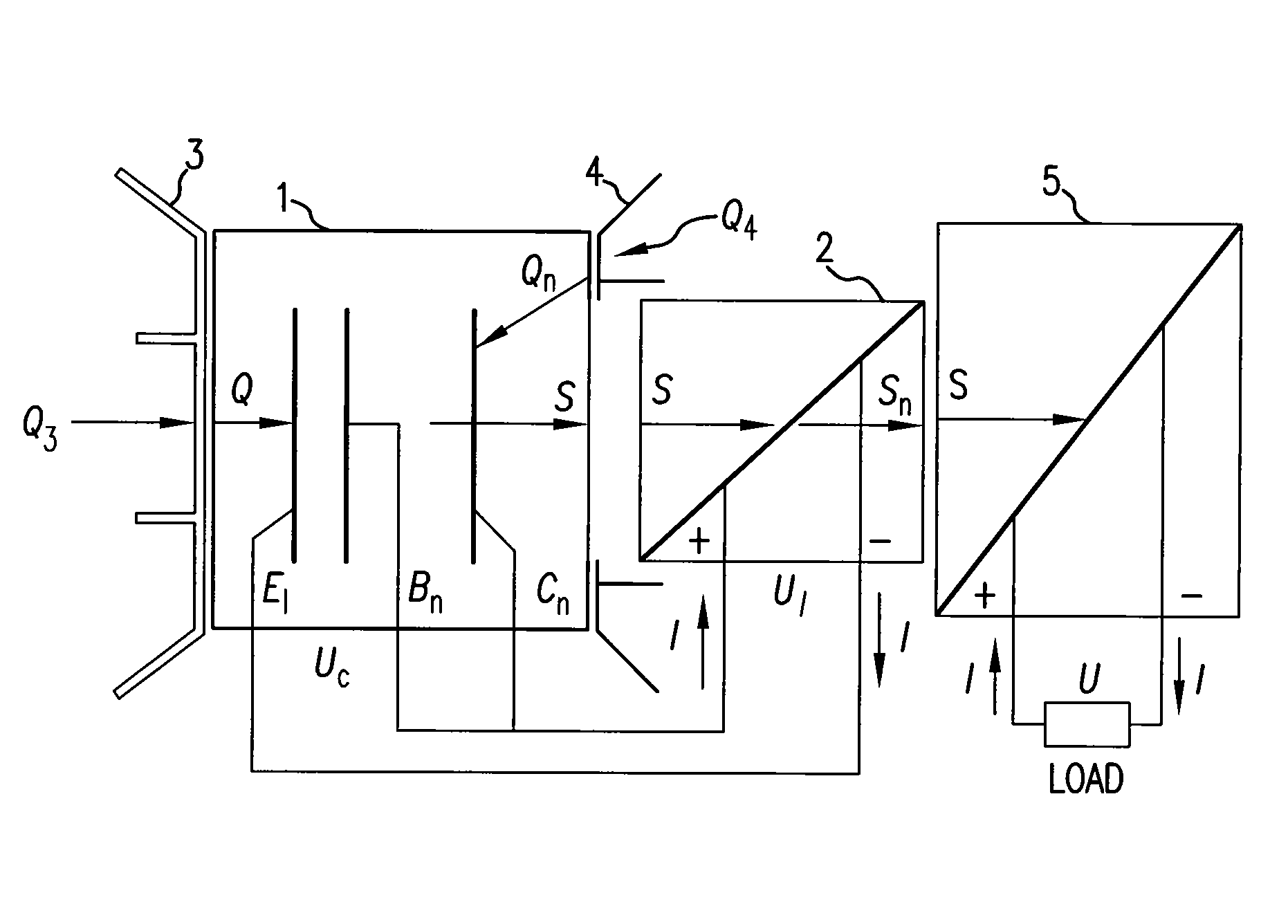
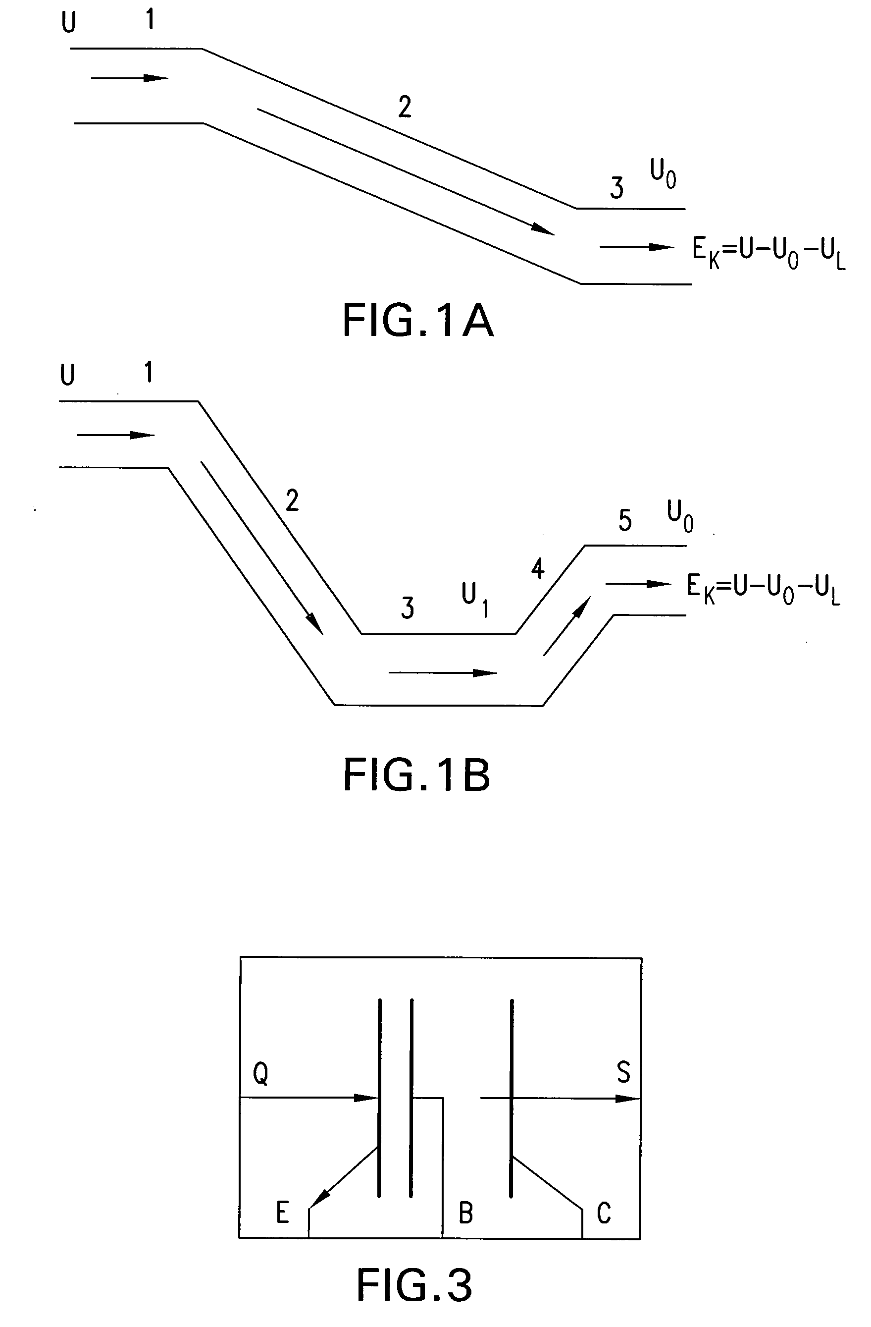
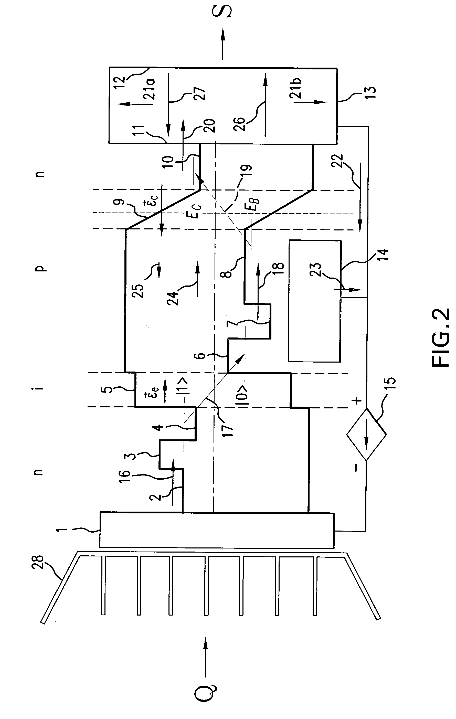
[0041]The present invention consists in a method and a semiconductor device for the coherent electromagnetic energy production on the account of the environment energy, by an electron transfer in two steps: (1) a super radiant decay, and (2) a thermal excitation. These method and semiconductor device will now be detailed only by way of non limiting examples in relation with FIGS. 2 to 8.

[0042]As a preliminary remark, it has been noticed within the scope of the present invention, that the processes of electron decay and excitation by heat absorption depend essentially on the coupling of the active electrons with the conduction electrons, the crystal vibrations and respectively the free modes of the electromagnetic field.

[0043]According to a first aspect, the present invention concerns a longitudinal quantum heat converter as represented in FIG. 2. The semiconductor device comprises an n-i-p-n structure 2-10, a double array of quantum dots 4 and 6 on the two sides of the thin i-layer ...


PUM


Abstract

A method for the environment heat conversion in coherent electromagnetic energy by a super radiant quantum decay and a thermal excitation of a system of electrons is disclosed. A semiconductor device is also disclosed comprising a system of n-i-p-n transistors, a double array of quantum dots on the two sides of the thin i-layer of the n-i emitter, a system of intermediate n and p layers separating the active quantum region from the n and respectively p regions by potential barriers, a metal front electrode, a heat absorber in intimate contact with this electrode, a semitransparent rear electrode forming with the front electrode a Fabry-Perot resonator tuned with the electron quantum transition frequency through the i-layer, and an output semitransparent mirror of the same transparency as the transparency of the rear electrode, by this forming with the rear electrode a total transmission Fabry-Perot resonator.

Description

FIELD OF INVENTION[0001]The present invention generally concerns a quantum heat converter for producing coherent electromagnetic energy on the account of the environmental heat. More particularly, the invention refers to a method and a quantum device converting heat in usable coherent electromagnetic energy by super radiant transitions supplied by an injection of electrons.BACKGROUND OF THE INVENTION[0002]First of all, if one considers the growing needs nowadays for new sources of energy and more especially of clean and renewable energies, as well as cooling issues for the planet, new solutions have to be developed. Many efforts have been recently done in connection with energies such as solar radiation, hydraulic power of tides or wind, etc. Nevertheless, all these energies require huge installations such as fields of solar panels or wind turbines or hydroelectric power stations and long distribution networks. Furthermore, the amount of energy produced is very low in comparison to ...

Claims


Application Information

Patent Timeline
Patent Type & Authority Applications(United States)
IPC IPC(8): H01L35/00H01L31/0352H01S5/32
CPCB82Y20/00H01S5/3412H01S5/04
Inventor STEFANESCU, ELIADECORNESCU, LUCIEN EUGENE
Owner STEFANESCU ELIADE
Why Eureka
Try Eureka