Charging apparatus

Active Publication Date: 2009-01-08
PANASONIC CORP
View PDF2 Cites 23 Cited by
  • Summary
  • Abstract
  • Description
  • Claims
  • Application Information

AI Technical Summary

Benefits of technology

[0015]The present invention provides a charging apparatus that overcomes conventional inconvenience and has high reliability.
[0019]In the charging apparatus according to the present invention, constant power is applied to the charging element with such a configuration, so that the internal temperature of the charging element loaded on the charging apparatus rises mildly. Consequently, the rise in the internal temperature of the charging element can be prevented. Because the internal temperature of the charging element can be suppressed to a low level, thermal shock generated each time when a vehicle is started can be reduced, thereby improving reliability of the charging element.

Problems solved by technology

In that case, if no other thing but the battery is provided, hydraulic control cannot be performed when supply of electricity is interrupted for some reason, so that braking of the vehicle is disabled.
However, as evident from FIG. 14B, loss power W lowers gradually as a charging time passes.
A problem caused by such a temperature change is that the inside of charging element 1 is placed under a high temperature condition by loss power W. In a word, every time the vehicle is started, the inside of charging element 1 receives a thermal shock.

Method used


Image

  • Charging apparatus
  • Charging apparatus
  • Charging apparatus

Examples


first embodiment

[0061]FIGS. 1 to 3C concern a first embodiment of the present invention.

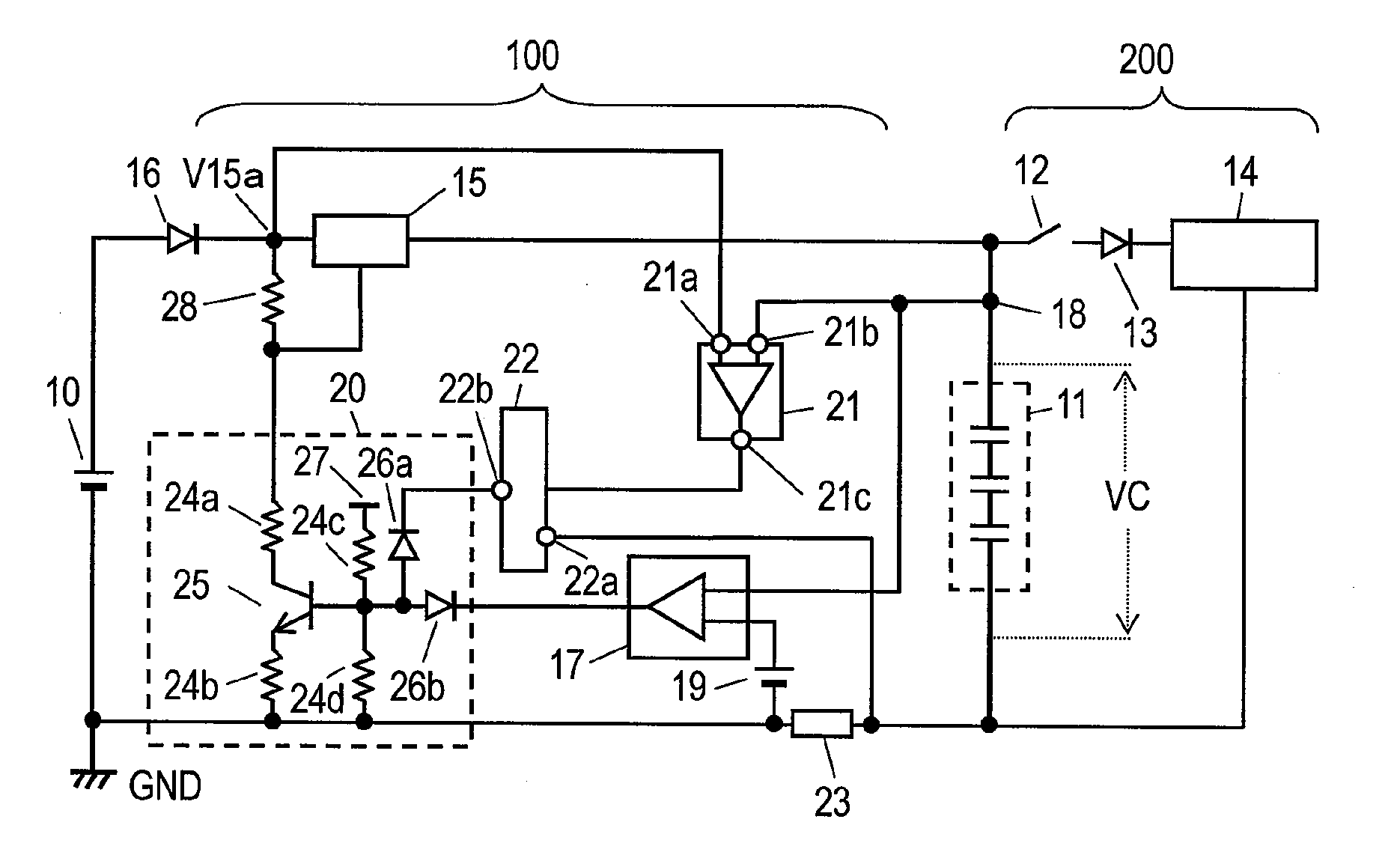
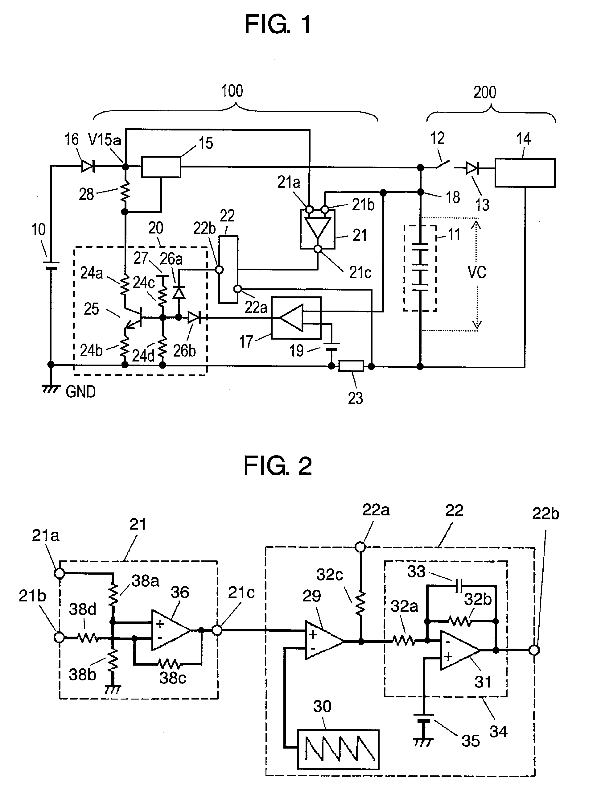
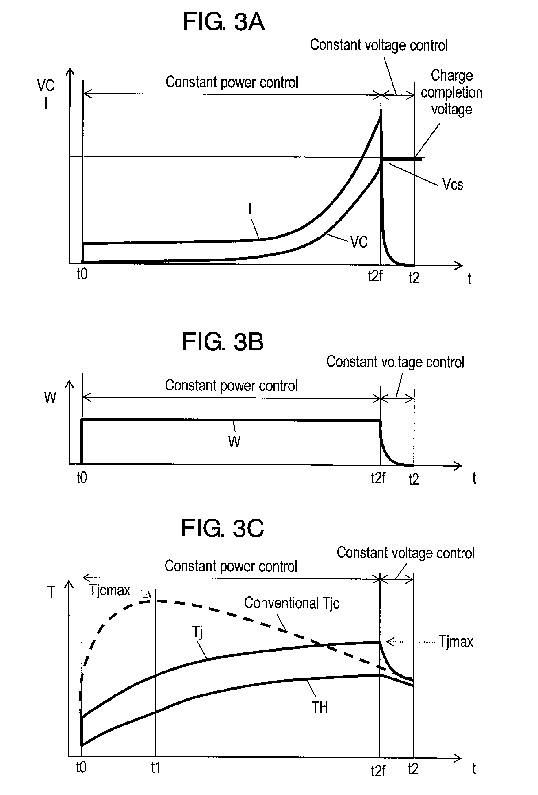
[0062]FIG. 1 is a block circuit diagram of a charging apparatus. FIG. 2 is a circuit diagram of a voltage detecting portion and an integrator of the charging apparatus. FIG. 3A shows change over time in charging current of a capacitor and voltage generated in the capacitor. FIG. 3B shows change over time in loss power of a charging element. FIG. 3C shows change over time in internal temperature and surface temperature of the charging element.

[0063]In FIG. 1, DC (direct current) power supply 10 and capacitor 11 are connected to charging apparatus 100. DC power supply 10 supplies charging apparatus 100 with electric power, and electric charge is accumulated in capacitor 11 by electric power of DC power supply 10.

[0064]Capacitor 11 is constructed of an electric double layer capacitor. Consequently, not only rapid charging is enabled but also large electric power can be discharged for the braking of a vehicle in an ...

second embodiment

[0087]FIGS. 4 to 6C show a charging apparatus according to a second embodiment of the present invention. FIG. 5 is a circuit diagram of a voltage detecting portion, a power switching portion and an integrator of the charging apparatus. FIGS. 6A, 6B and 6C show change over time of the charging apparatus during a charging operation. FIG. 6A shows change over time in the charging current and capacitor voltage of the capacitor, FIG. 6B shows change over time in loss power of the charging element and FIG. 6C shows change over time in the internal temperature and surface temperature of the charging element.

[0088]In FIGS. 4 and 5, the same reference numerals designate the same components as in FIGS. 1 and 2.

[0089]The second embodiment is different from the first embodiment in that power switching portion 37 is connected between terminal 21c of voltage detecting portion 21 and integrator 22.

[0090]As shown in FIG. 5, the second embodiment is provided with power switching portion 37 constitut...

third embodiment

[0106]FIGS. 7 to 8C show a charging apparatus according to a third embodiment of the present invention.

[0107]FIG. 7 is a block circuit diagram of the charging apparatus. FIG. 8A shows change over time in the capacitor charging current and capacitor voltage, FIG. 8B shows change over time in the loss power of the charging element, and FIG. 8C shows change over time in the internal temperature and surface temperature of the charging element.

[0108]In FIG. 7, like reference numerals denotes the same components as in FIG. 1. The third embodiment shown in FIG. 7 is provided with current limiting portion 40 and diode 41 in addition to the structure described in the first embodiment. For example, current limiting portion 40 is constructed of a differential amplifier, and a voltage of current detecting portion 23 and reference voltage 19 are provided to each of two inputs of current limiting portion 40 separately. An output terminal of current limiting portion 40 is connected to control synt...


PUM


Abstract

A charging apparatus suppresses rise in temperature of an internal chip of a charging element. The output signal obtained from a current detecting portion for detecting charging current to a capacitor and from a voltage detecting portion for detecting a difference between a voltage (VC) of capacitor and a voltage corresponding to DC power supply is integrated by integrator. The charging is carried out by controlling power of a charging element to a predetermined value using an output signal of the integrator and at a time near the completion of the charging, the charging element is controlled by constant-voltage-control-circuit so as to charge the capacitor up to a predetermined voltage. Consequently, the maximum temperature inside the charging element is reduced, thereby providing a charging apparatus with high reliability.

Description

TECHNICAL FIELD[0001]The present invention relates to a charging apparatus for charging a capacitor rapidly.BACKGROUND ART[0002]In recent years, development of hybrid cars and electric vehicles has been advanced rapidly and accompanied by this, a braking method of a vehicle has been changed from a conventional mechanical hydraulic control method to an electric hydraulic control method, so that a variety of control methods have been proposed.[0003]Generally, the battery is used as a power supply in order to control hydraulic pressure of a vehicle electrically. In that case, if no other thing but the battery is provided, hydraulic control cannot be performed when supply of electricity is interrupted for some reason, so that braking of the vehicle is disabled.[0004]Therefore, there has been proposed a charging apparatus equipped with a so-called auxiliary power supply in order to cope with an emergency by equipping a large-capacity capacitor or the like as the auxiliary power supply in...

Claims


Application Information

Patent Timeline
IPC IPC(8): H02J7/00
CPCH02J7/0091H02J7/007194
Inventor ODAJIMA, YOSHIMITUTAKEMOTO, JUNJIMORITA, KAZUKI
Owner PANASONIC CORP
Why Eureka
Try Eureka