Data transfer device and data transfer method

a data transfer device and data transfer technology, applied in the field of data transfer devices, can solve the problems of increasing the cost of system implementation, complicated circuits, and enlarging circuits, and achieve the effect of simple comprisal

Inactive Publication Date: 2009-01-08
FUJITSU LTD
View PDF14 Cites 9 Cited by
  • Summary
  • Abstract
  • Description
  • Claims
  • Application Information

AI Technical Summary

Benefits of technology

[0013]Here, the one-cycle transfer volume calculation unit calculates the number of lines to be transferred in one cycle and the volume of data corresponding to the number of lines, and the invalid data addition unit adds invalid data to the data, stored in the buffer unit, corresponding to the number of lines so that the aforementioned data volume matches the calculated data volume. This configuration makes it possible to make a packet size a fixed length even for data to which a variable length coding has been applied, satisfying the specification of a fixed bit rate required when carrying out an isochronous transfer in a low cost system using, for example, the IEEE 1394 interface, thereby making it possible to transfer image data in real time with a simple comprisal.
[0015]The image data transfer device according to the third aspect is configured to set the number of lines to be made, for example the fixed length being no less than the number of lines of the image data to be transferred in one cycle, making it possible to make the data length of a larger number of lines be a fixed length, thereby enabling an easier monitoring of a coding volume performed by the coding volume monitor unit comprised in a system.
[0018]The present invention makes it possible to change the packet size of data, to which a variable length coding is applied, to be a fixed length, satisfying the specification of a fixed bit rate required when carrying out an isochronous transfer and making it possible to transfer data in real time with a simple comprisal.

Problems solved by technology

This results in complicating a circuit, enlarging the circuit size, and increasing the cost in implementing a system.

Method used


Image

  • Data transfer device and data transfer method
  • Data transfer device and data transfer method
  • Data transfer device and data transfer method

Examples


embodiment 1

[0059]{Description of Comprisal}

[0060]The present invention aims at providing a system (i.e., a data transfer device) accomplishing a requirement in a simple comprisal and at a low cost when real-time performance is required of the transmission of image data.

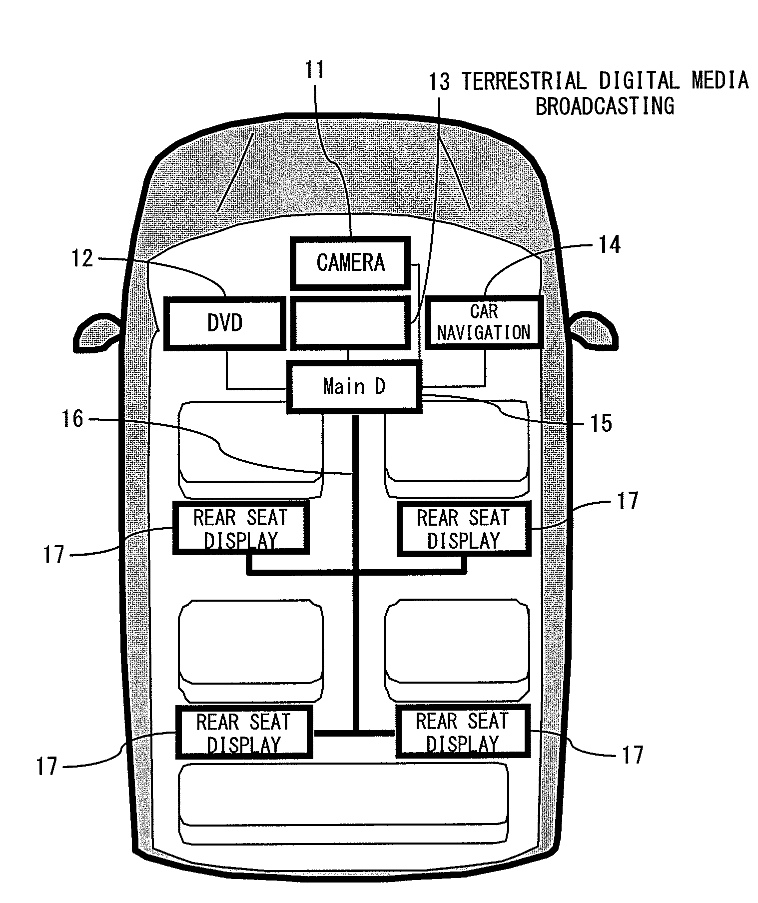
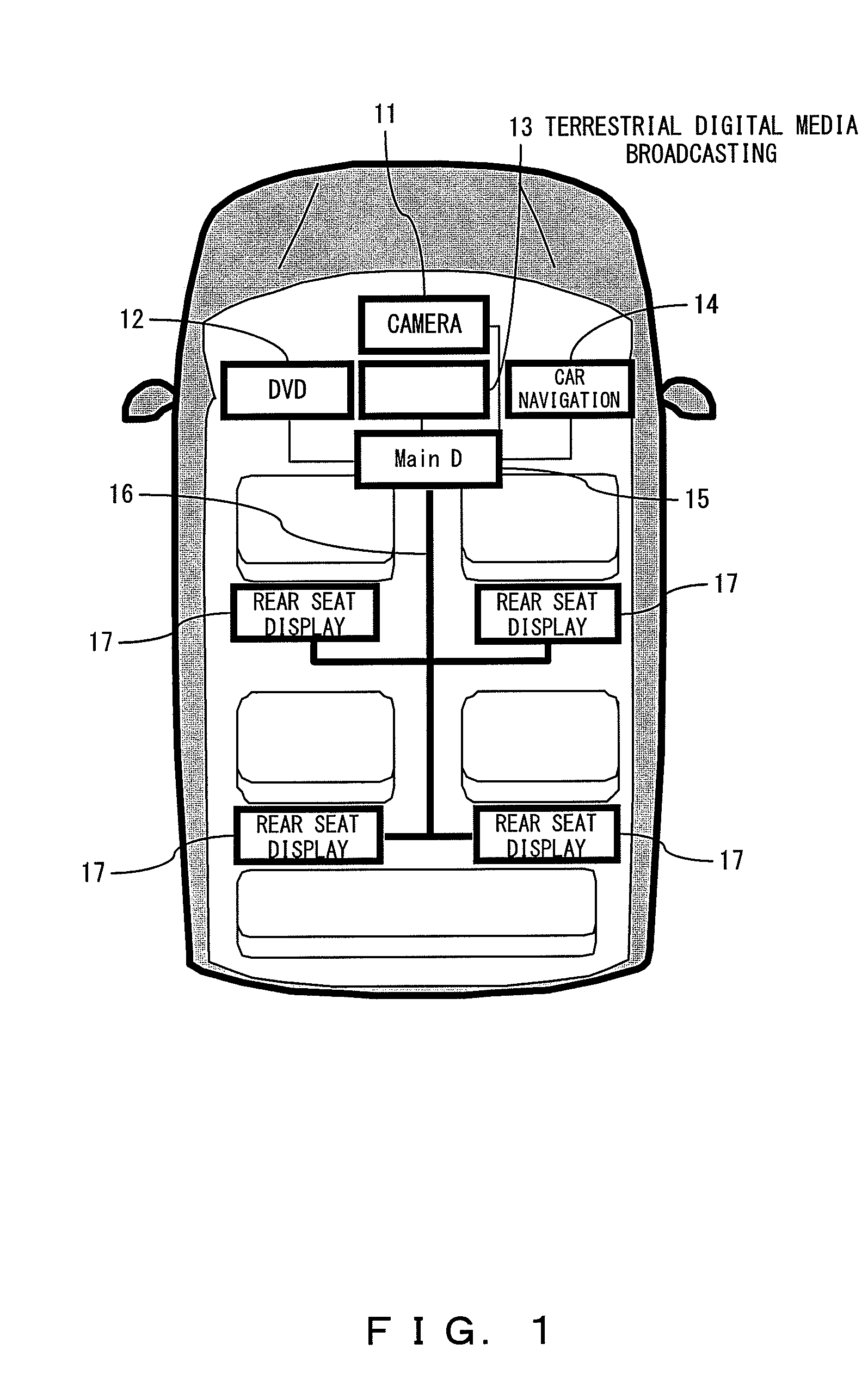
[0061]Such a system includes an on-vehicle transfer system for image data as shown in FIG. 1.

[0062]Referring to FIG. 1, the camera 11 imports an image at a spot that tends to be a blind spot in the vision of a driver, such as the side of the road and behind the vehicle (an automobile in this case), and outputs the image in a main display device 15 and a display device(s) 17 located in a rear seat connected to the main display device 15 via a bus 16.

[0063]A digital versatile disk (DVD) player 12 replays a DVD. A terrestrial digital media broadcast-use tuner 13 tunes to a terrestrial broadcasting wave, converts it into a video image signal, and then outputs image data to the main display device 15 and display device 17 in a rear s...

embodiment 2

[0131]Next is a description of a preferred embodiment 2, which is an exemplary modification of embodiment 1.

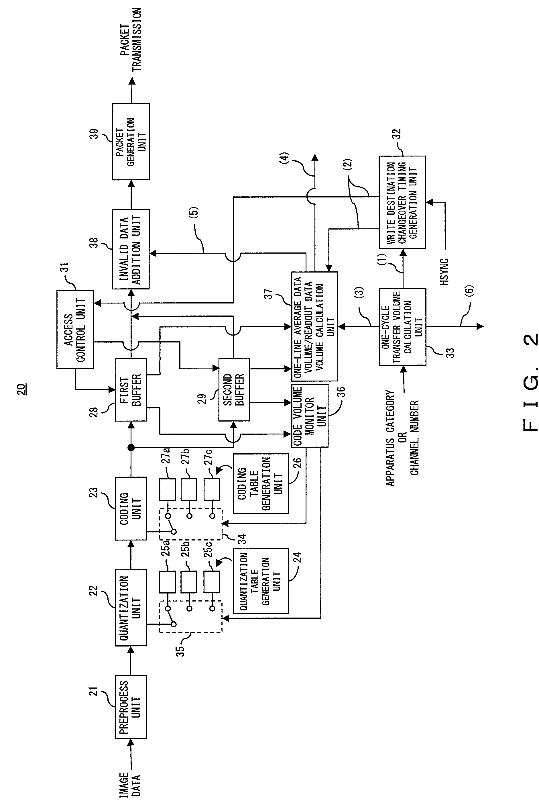
[0132]The header part of the above described embodiment 1 includes information such as information indicating the position of an HSYNC (horizontal synchronous) signal for determining the readout timing for each line of image data and the size of the image data (e.g., the number of lines and the number of pixels per line).

[0133]If data is decoded at a node on the reception side, it is preferable that the data include invalid data at a constant ratio. Because of this, the above description has handled the case of invalid data being appropriately distributed in the substance data of an isochronous packet.

[0134]Invalid data, however, may also be added at one place in either the head or tail of the substance data of an isochronous packet.

[0135]In such a case, compared with FIG. 2, the one-line average data volume / readout data volume calculation unit 37 is replaced with an invalid d...

embodiment 3

[0141]The following handles the case of making a fixed length for a number of lines exceeding the number of lines to be transferred in one cycle. Also in this case, what are considered here are, as with the above description, a case in which invalid data is appropriately distributed in the substance data region of an isochronous packet and a case in which invalid data is added at the head or tail of the substance data region of an isochronous packet.

[0142]In the case of making a fixed length for the number of lines exceeding the number of lines to be transferred in one cycle, if invalid data is appropriately distributed, when receiving an input of the category of device or a channel number, the one-cycle transfer volume calculation unit 33 shown in FIG. 2 calculates (i.e., obtains) the number of lines to be transferred in one cycle, the number of lines to be changed to a fixed length, and the number of bytes corresponding to the number of lines to be changed to a fixed length, all o...


PUM


Abstract

The present invention aims at providing an image data transfer device capable of transferring image data in real time with a simple comprisal. The device according to the present invention calculates both the number of lines of the image data to be transferred in one cycle and the volume of data corresponding to the aforementioned number of lines on the basis of the category of the image data, stores data in an amount that is equivalent to the aforementioned number of lines of the image data processed by a variable length coding, calculates the difference between the calculated data volume corresponding to the number of lines and the volume of data stored, adds invalid data to the data stored in an amount that is equivalent to the calculated difference and generates, transmits a packet on the basis of the data to which the invalid data has been added.

Description

CROSS REFERENCE TO RELATED APPLICATION[0001]This application is a continuation of PCT application of PCT / JP2006 / 315053, which was filed on Jul. 28, 2006.BACKGROUND OF THE INVENTION[0002]1. Field of the Invention[0003]The present invention relates to a data transfer device transferring data by compressing it.[0004]2. Description of the Related Art[0005]Image data is commonly transferred in compressed form using a compression method such as the Moving Picture Experts Group (MPEG) 2, et cetera. When data is transmitted in the MPEG 2 system, the MPEG2-TS format is often used. In this format, the data that is actually transferred is encapsulated within a 188-byte fixed length together with various control data.[0006]When an attempt is made to attain an environment in which a real time performance such as a transmission of a motion image is required, what is required with the MPEG2 method is to store information such as a time stamp for avoiding a temporal synchronization in the header pa...

Claims


Application Information

Patent Timeline
Patent Type & Authority Applications(United States)
IPC IPC(8): H04N7/26H04N7/16H04N19/00H04N7/173H04N19/70H04N19/91
CPCH04N7/163H04N21/41422H04N21/43615H04N21/44231H04N21/4402H04N21/44227H04N21/44004
Inventor NAKANO, YASUHIKO
Owner FUJITSU LTD
Why Eureka
Try Eureka