Seal ring and associated method

a sealing material and seal technology, applied in the field of sealing materials and seal rings, can solve the problems of affecting the life of the bonding part, and affecting the sealing effect of the sealing glass,

Active Publication Date: 2009-01-08
GENERAL ELECTRIC CO
View PDF10 Cites 36 Cited by
  • Summary
  • Abstract
  • Description
  • Claims
  • Application Information

AI Technical Summary

Benefits of technology

[0010]In accordance with an embodiment of the invention, a method of forming a seal ring is provided that is capable of sealing an energy storage device. The seal ring has a high metal content first portion, or is weldable at that first portion; and, has a high metal content second portion, or is weldable at that second portion. And, the first portion is electrically isolated from that second portion by an electrically insulating portion.

Problems solved by technology

The seal glass may have undesirable characteristics associated with its use.
Bonded parts formed from dissimilar materials in a high temperature cell may crack resulting due to thermal stress caused by mismatch in the coefficient of thermal expansion.
The bond may have a limited life, and bond failure may cause cell failure.

Method used


Image

  • Seal ring and associated method
  • Seal ring and associated method

Examples


example 1

Forming a Seal Ring

[0040]A cylindrical pressing form is filled with a suspension of cermet (alumina, refractory metal) particles made with polyvinyl organic binder. A piston presses and forms the suspension at an elevated temperature to form a first green portion that will ultimately form the first weldable portion. A uniaxial press with a pressure of 40 ksi is applied. After the piston is withdrawn, a second suspension is filled into the form in contact with the first green portion. The second suspension includes electrically insulative alumina powder and PVA binder. The piston presses and heats the intermediate component to form a second green portion. After the piston is withdrawn, a third cermet suspension (with binder and refractory metal powder) is filled into the form in contact with the second green portion. The metal content of the first and third suspensions is sufficient to allow for welding subsequent to manufacture. Particularly, the first suspension has about 50 percen...

example 2

Sealing an Energy Storage Device

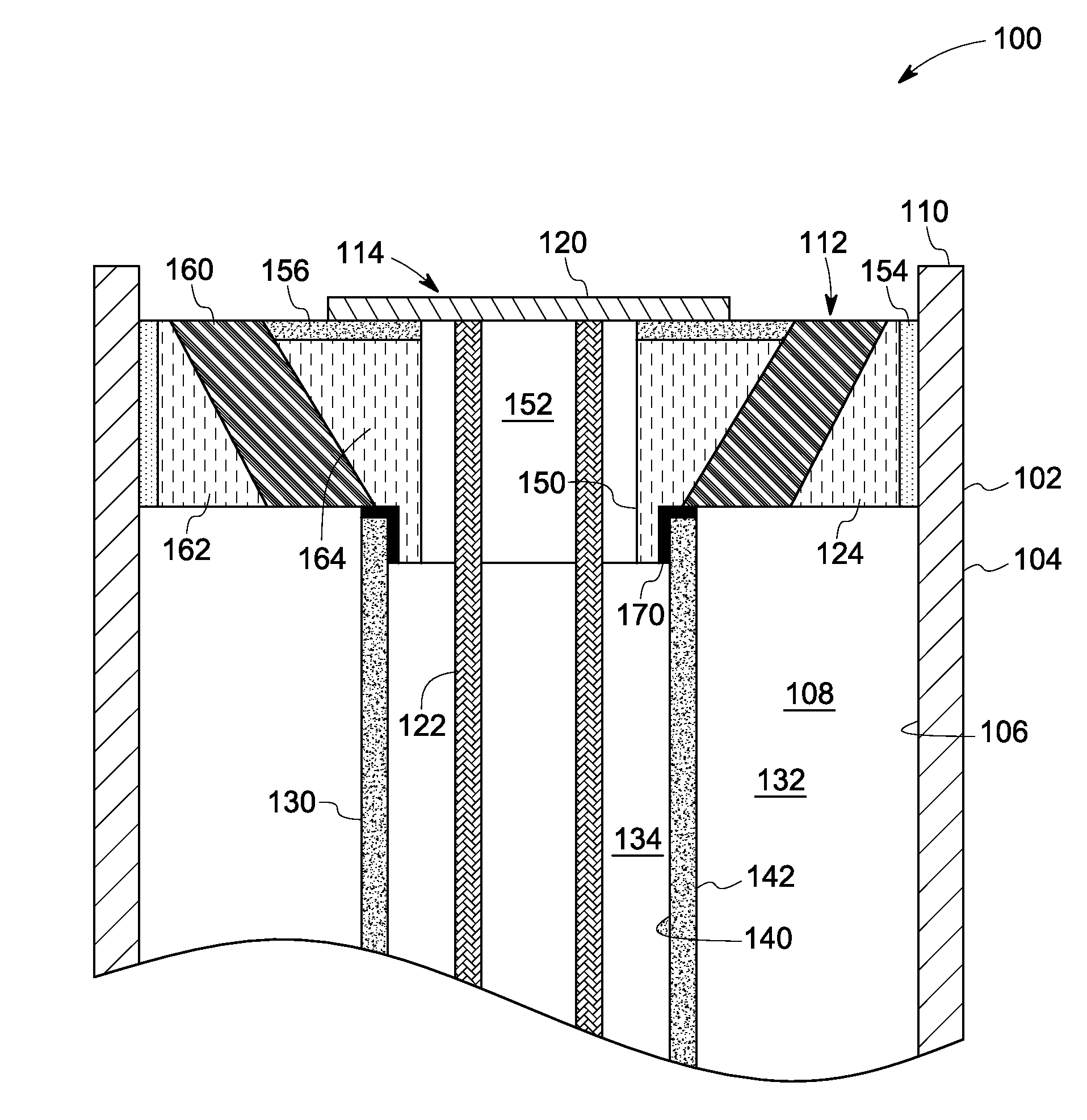
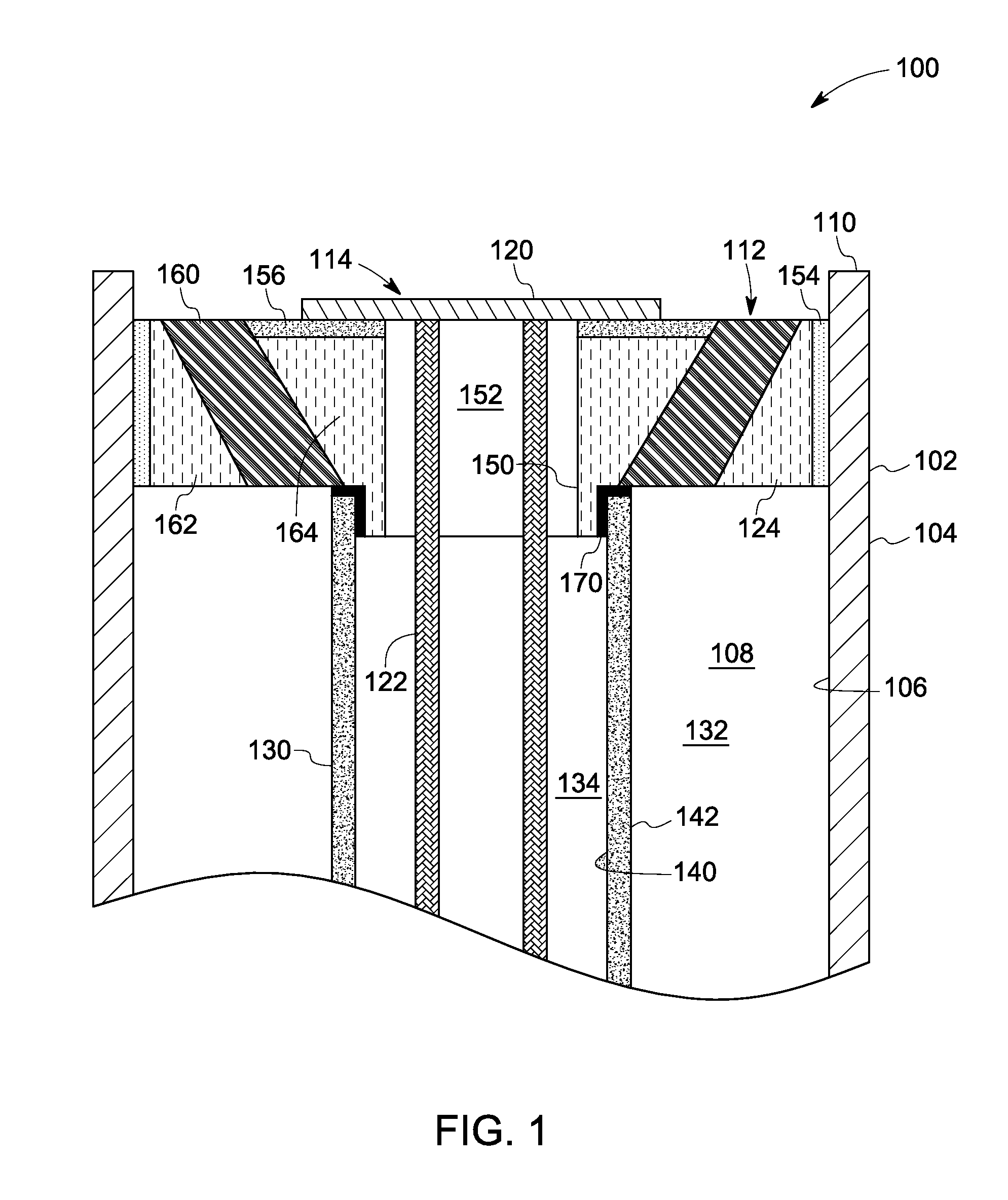
[0042]A seal ring is formed as disclosed in Example 1. The seal ring is secured to a separator via a glass seal to form a seal ring assembly. The seal ring assembly is disposed in an energy storage device housing. A cap with a current collector is inserted into the seal ring aperture so that the current collector is in contact with a cathode fill material that is inside the separator. Alternatively, a ring or bridge piece with a current collector is inserted into the seal ring aperture. In a single substantially continuous process, the first and second weldable portions of the seal ring are welded to the housing inner surface and to the cap, respectively. The cathode materials can be added through the aperture in the bridge piece. The cap is then welded to the bridge piece. The weldable portions flow and seal with their respective mating surfaces to form a hermetic weld structure.

example 3

Sealing an Energy Storage Device

[0043]A seal ring is formed as disclosed in Example 1. The seal ring is welded to the inner surface of the can using an arc welding process. In particular, a tungsten inert gas (TIG) welding process is used. Cathode material is filled into the separator inner volume. A cap is placed over the seal ring aperture to contact another weldable portion of the seal ring. The cap is welded to the seal ring using either the TIG process or the Plasma Arc Weld method (PAW). The energy storage device produced as in this example allows for the pre-production of the housing, seal ring, and separator sub-component. It is noted that other minor components of the energy storage device have been omitted for clarity. Such components may include a support shim for the separator, a wick for the anode material, and the like. These listed components may be disposed in an anode chamber, and pre-production approaches, such as in this example, may allow for increased productivi...


PUM

PropertyMeasurementUnit
pressureaaaaaaaaaa
temperatureaaaaaaaaaa

Abstract

An article includes a seal ring for an energy storage device. The seal ring has a weldable first portion and a weldable second portion. The first and second portions are electrically isolatable from each other by an electrically insulating third portion.

Description

BACKGROUND[0001]1. Technical Field[0002]The invention includes embodiments that relate to a sealing material and seal ring for an energy storage device. The invention includes embodiments that relate to a method of sealing an electrochemical cell.[0003]2. Discussion of Related Art[0004]Development work has been undertaken on high temperature rechargeable batteries using sodium for the negative electrodes. The liquid sodium negative electrode is separated from a positive electrode by a sodium-ion conducting solid electrolyte. Suitable material includes beta alumina and beta” alumina, known as beta alumina separator electrolyte (BASE). Some electrochemical cells have a metallic casing. Interior parts of the battery and the metallic casing may seal to interior parts of the battery. The ceramic parts of the cell can be joined via a seal glass. The seal glass may have undesirable characteristics associated with its use. Metallic parts can be joined by welding or thermal compression bondi...

Claims


Application Information

Patent Timeline
Patent Type & Authority Applications(United States)
IPC IPC(8): H01M2/08H01M4/82H01M50/184H01M50/186H01M50/191H01M50/533H01M50/541
CPCC04B35/6455C04B37/021C04B2235/661C04B2237/343C04B2237/403C22C1/051Y10T29/4911H01M2/08H01M8/0276H01M8/0282H01M8/0286H01M10/3909Y02E60/50C22C29/12Y02E60/10H01M50/184H01M50/186H01M50/191H01M50/533H01M8/028H01M8/0271
Inventor STRINGER, CRAIGIACOVANGELO, CHARLES DOMINICDALPE, DENNIS JOSEPHVARTULI, JAMES SCOTTBREWER, JAMES ANTHONY
Owner GENERAL ELECTRIC CO
Why Eureka
Try Eureka