Differential mechanism assembly

a technology of differential mechanism and assembly, which is applied in the direction of transportation and packaging, other domestic objects, and gearing, etc., can solve the problems of difficult material flow in the tangential direction and easy attainment of non-uniform thicknesses in the longitudinal direction, so as to simplify laser welding and reduce manufacturing costs. , the effect of saving additional costs

Inactive Publication Date: 2009-01-15
FORD GLOBAL TECH LLC
View PDF3 Cites 21 Cited by
  • Summary
  • Abstract
  • Description
  • Claims
  • Application Information

AI Technical Summary

Benefits of technology

[0014]Because the surface finish of the mandrel is imprinted onto the interior of the case, no machining is required on the inside of the case, thereby reducing manufacturing cost. Automated assembly of components within the case is accomplished through an open end of a bell-shaped case, rather than through windows, thereby saving additional cost.
[0015]The similarity in carbon equivalent between the steel differential case and a steel ring, as compared to a steel ring and cast iron case, simplifies laser welding. The elimination of bolts and holes, and frequent errors in bolt hole position, reduces weight and manufacturing error.
[0016]The differential case portions are of a low carbon steel or a low carbon micro-alloyed steel, rather than nodular (also called ductile) cast iron, thereby providing a higher elastic modulus. Cold flow forming the case provides work hardening and adds to case strength and wall thickness optimization. The direct drive design allows the case wall thickness to be reduced by removing the case from the torque path. Laser welding, or some other appropriate welding process, is employed to attach one or more of the case components to the ring gear, with the internal components inserted through the open end of the flow formed case, rather than through a window in a one-piece cast design. A flange, used to bolt-on the ring gear in the baseline design, may be removed from some embodiments. Flow forming from a sheet blank and a forged blank are available to result in the desired thickness distribution.
[0017]Improved s

Problems solved by technology

Causing material to flow in the tangential direction is difficult.
But the desired, non-uniform thicknesses are easily achieved in the longit

Method used


Image

  • Differential mechanism assembly
  • Differential mechanism assembly
  • Differential mechanism assembly

Examples


case portion 13

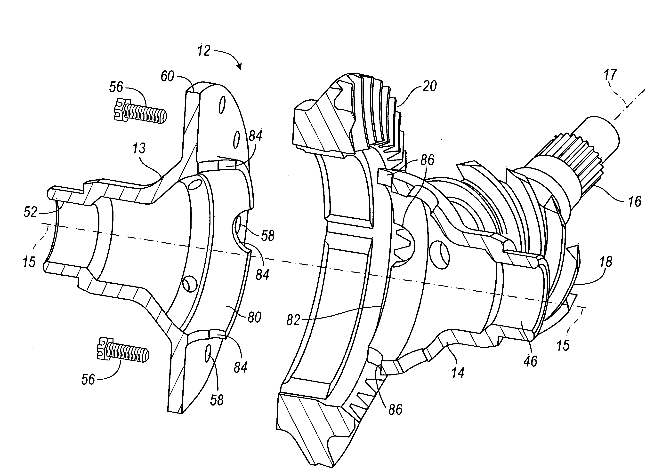
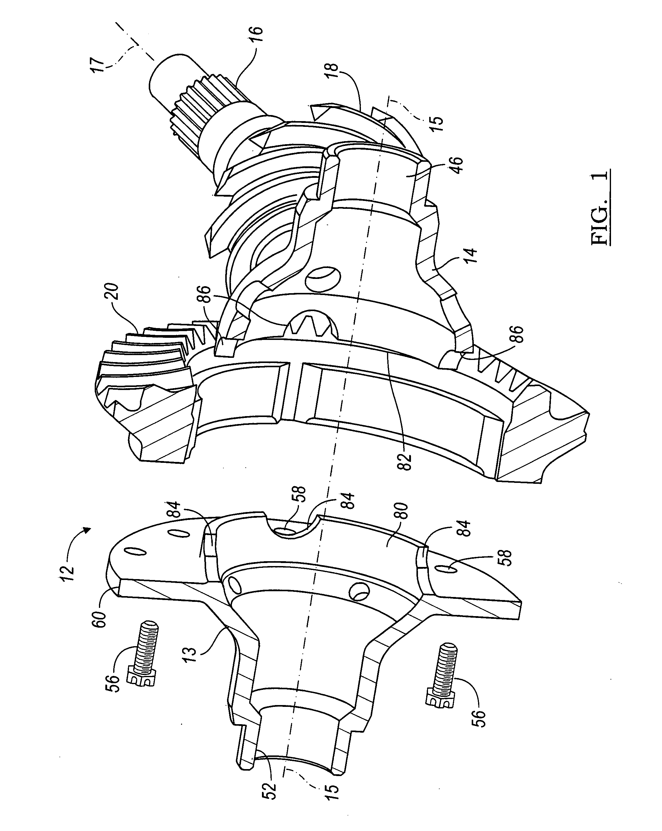
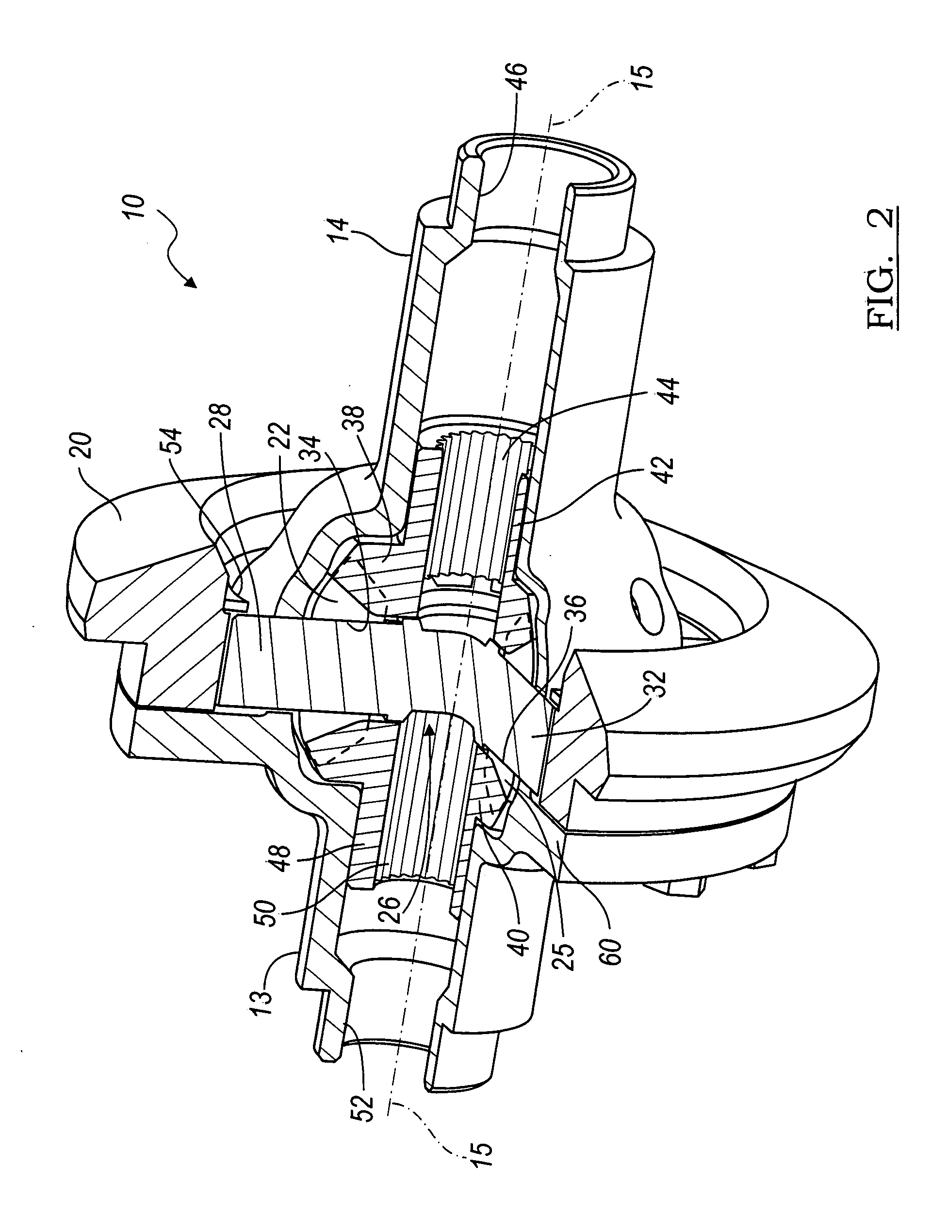
[0047]Case portion 13 includes an axial protrusion 80, which contacts an annular rim 82 on case portion 14, when the parts are assembled. The axial protrusion 80 is formed with a series of arcuate recesses 84, spaced angularly about axis 15. Each recess 84 partially surrounds a respective spider pin 28, 30, 32 (as shown in FIG. 6) and is aligned with a spider pin hole portion 86 formed in case portion 14. Each recess 84 and hole portion 86 complete a circular or slotted hole 88, which contains a spider pin 28, 30, 32 when the case is assembled.

[0048]FIGS. 3 and 4 illustrate an alternative embodiment of a differential assembly 62, in which two differential case portions 64, 66 are secured mutually and to a ring gear 67 by a series of bolts, each bolt being fitted into a hole 68 located on a circle of bolt holes formed in a radial flange 70 on case portion 64 and a hole 72 located on a circle of bolt holes formed in a radial flange 74 and aligned with a hole 68 on case portion 66. Fla...

case portion 64

[0050]Case portion 64 includes an annular, axial-extending protrusion 80, which contacts an annular rim 82 on case portion 66, when the parts are assembled, as shown in FIG. 4. The axial protrusion 80 is formed with a series of arcuate recesses 84, spaced angularly about axis 15. Each recess 84 partially surrounds its respective spider pin 28, 30, 32 and is aligned with a spider pin hole portion 86 formed in case portion 66. Each recess 84 and hole portion 86 complete a circular hole 88, which contains a spider pin 28, 30, 32 when the case is assembled as shown in FIG. 4.

[0051]FIG. 5 illustrates the pinions 22-25 supported on a case portion 14, 66 for rotation about the spider pins 28, 30, 32. FIG. 6 shows parallel slots 90 formed at diametrically opposite sides of spider pin 30, and parallel slots 92 formed at diametrically opposite sides of spider pin 32. A clip 94 includes legs 96, 97, each of which engages a slot 90 on spider pin 30, and legs 98, 99, each of which is similar res...

first embodiment

[0055]FIG. 10A shows the first embodiment, the open differential 10 of FIGS. 1-4, whose case portion 13 includes the annular, axial-extending protrusion 80.


PUM

PropertyMeasurementUnit
Thicknessaaaaaaaaaa

Abstract

A method for manufacturing a differential assembly, comprising producing a first case portion by cold flow forming a first workpiece on a first mandrel, producing a second case portion by cold flow forming a second workpiece on a second mandrel, installing in a cavity formed in the first case portion a spider assembly including radially extending spider pins located at an axial position, pinions supported for rotation on the spider assembly, and a first side gear engaged with the pinions, installing in a cavity formed in the second case portion a second side gear engaged with the pinions, and securing the second case portion to the first case portion.

Description

BACKGROUND OF THE INVENTION[0001]1. Field of the Invention[0002]This invention relates generally to a differential gear mechanism for transmitting rotary power from a power source to the wheels of a vehicle so that the wheels can rotate at mutually differential speeds and to the manufacture of the differential mechanism.[0003]2. Description of the Prior Art[0004]A differential mechanism transmits rotary power differentially to output shafts from a ring gear driven by an external power source, such as an internal combustion engine or electric motor. The differential ring gear, usually a hypoid bevel gear, is secured to the differential case, which is generally produced of cast nodular or ductile iron for high torque applications. The case is secured to the ring gear and defines a chamber containing bevel pinions driveably connected to the case by pinion shaft or spider, depending on the number of bevel pinions used, a right-side bevel gear and a left-side bevel gear in continuous mes...

Claims


Application Information

Patent Timeline
IPC IPC(8): B23P15/14
CPCF16H48/08F16H48/40F16H2048/346F16H2048/282F16H2048/382Y10T29/49465F16H48/22F16H48/28F16H2048/085Y10T74/2186Y10T29/49464F16H48/34B23P15/00B21D22/16F16H48/24
Inventor ISKEN, II, DENNIS W.STORY, JAMES M.KRYSZTOF, CHARLESNEAL, ROBERT J.SAVAGE, JASONSZCZEPANSKI, GERALD S.
Owner FORD GLOBAL TECH LLC
Why Eureka
Try Eureka