Reduction Process and Plant

Active Publication Date: 2009-01-15
DANIELI & C OFF MEC SPA
View PDF5 Cites 17 Cited by
  • Summary
  • Abstract
  • Description
  • Claims
  • Application Information

AI Technical Summary

Benefits of technology

[0033]A first purpose of the present invention is to produce a reduction process for the production of metallic iron that, by comprising a step in which a portion or all of the syngas entering the plant circuit is processed to separate the methane fro

Problems solved by technology

Since the quality of the product and the reaction kinetics, and thus the productivity of the plant, depend on this temperature, and since the plants connected to gasifiers according to the prior art are not provided with means for controlling the amount of methane in the reducing gas that is fed into the reactor, the possibility of controlling the process in the reaction zone of the reactor is extremely limited.
Furthermore, if the syngas that is used has a high methane content, this will result in excess methane in the reducing gas line entering the reactor with the consequence that the temperature in the reaction zone may be below that required for sufficient reduction of the oxide pellets.
A second drawback deriving from the fact that it is impossible to control the amount of methane in the reducing gas is the subsequently high levels of methane in the exhaust gas exiting the reactor.
If the gas that is generally used as fuel has a high calorific value, there may be a surplus of gas that would necessarily be sent to the torch, with a subsequent reduction in overall process efficiency.
Another drawback regards the fact that it is not easy to control the carburization process in the carburization zone.
Furthermore, direct reduced iron

Method used


Image

  • Reduction Process and Plant
  • Reduction Process and Plant
  • Reduction Process and Plant

Examples


Embodiment Construction

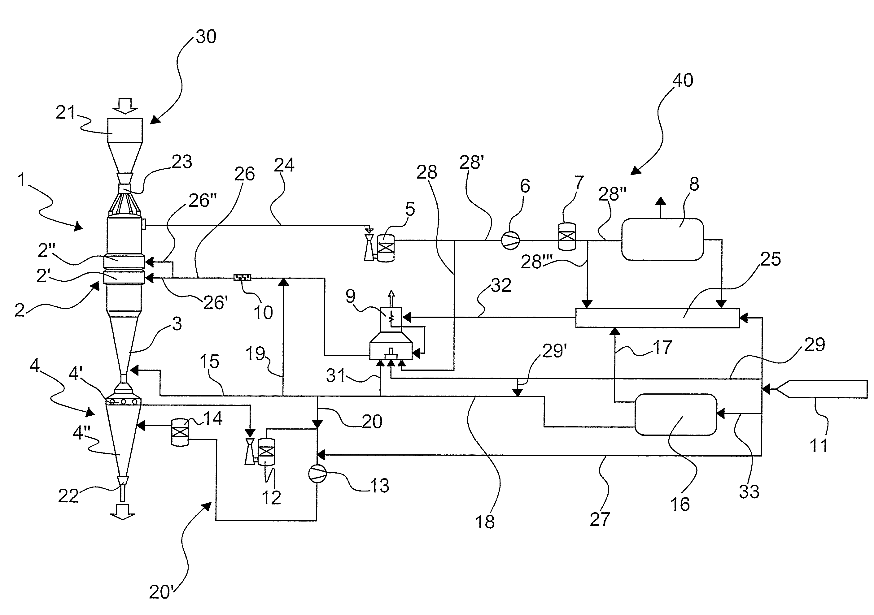
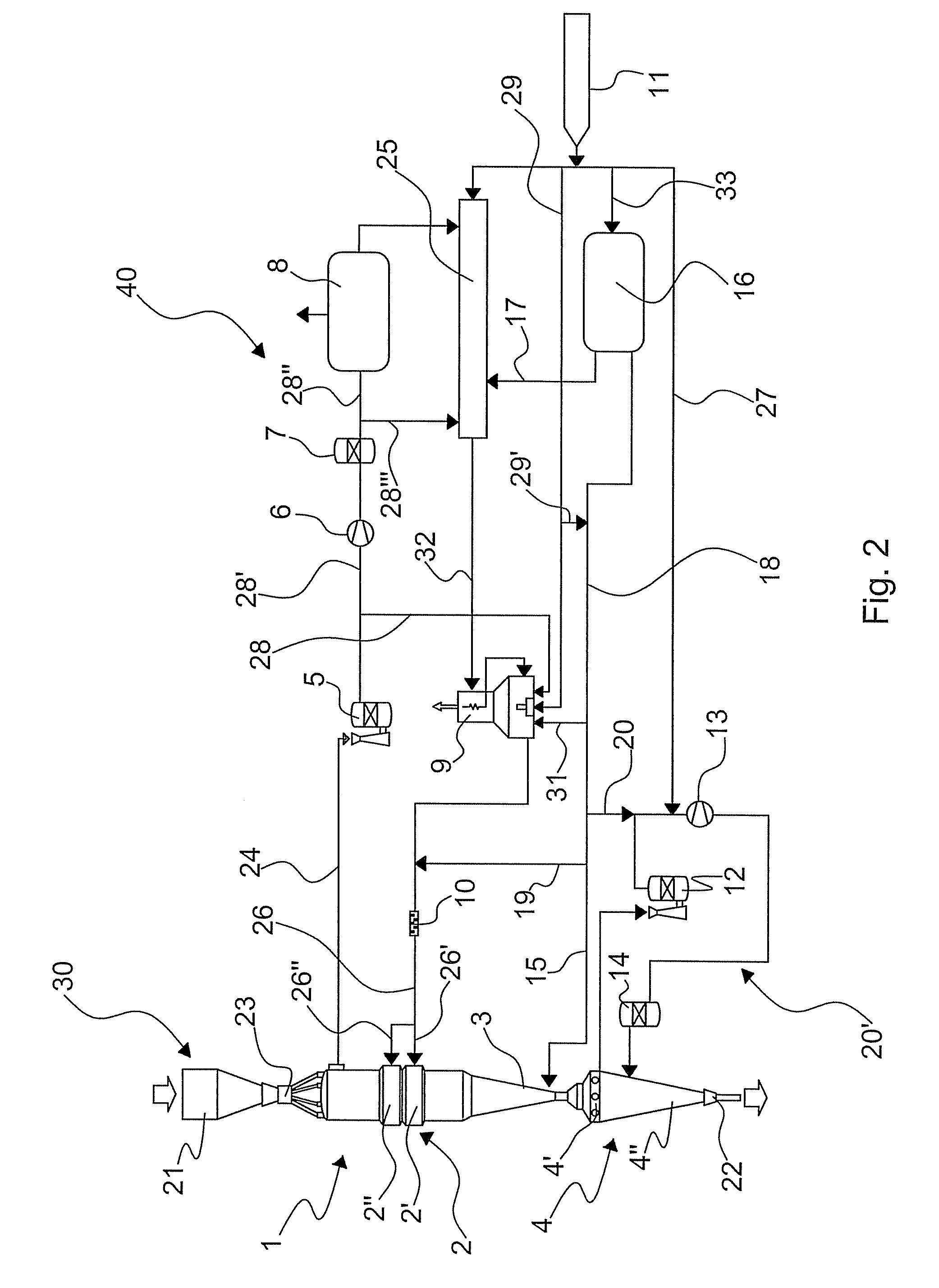
[0054]With reference to FIG. 2 a layout of a reduction plant suitable for performing the process according to the present invention is illustrated.

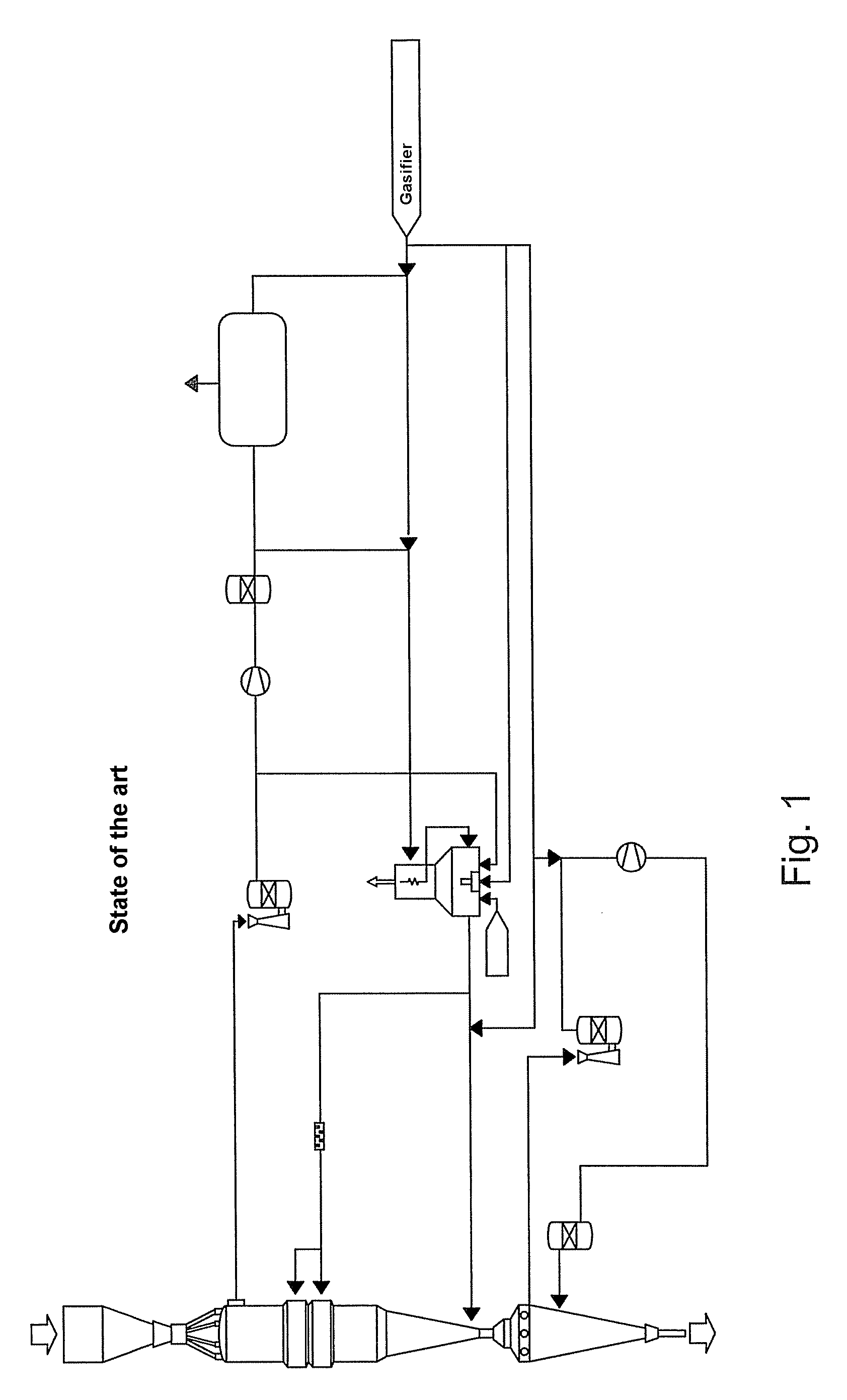
[0055]Said plant provides for the connection by means of a plant circuit, indicated as a whole by the number 40, of a reduction shaft 30 with an external source 11 supplying synthesis gas, otherwise known as syngas, which is used as the reducing gas and produced for instance by a coal gasifier.

The reduction shaft 30 comprises from top to bottom:[0056]an iron ore feeding zone 21,[0057]a reactor or shaft 1 for the direct reduction of the minerals,[0058]a carburization zone 3,[0059]a cooling vessel 4.

[0060]The reactor or shaft 1 produces hot metallic iron or DRI, from oxides in the form of pellets and / or lumps, that descends due to the effects of gravity into the carburization zone 3. The cooling vessel 4 downstream is in turn directly connected to a discharging device by means of a dynamic gas seal leg 22. A second dynamic gas seal leg 23 i...


PUM

PropertyMeasurementUnit
Temperatureaaaaaaaaaa

Abstract

Reduction process and relative plant for the production of metallic iron by means of the direct reduction of iron ore, in which a reduction shaft is connected to a source of reducing gas obtained from the gasification of coal. The process advantageously comprises a step in which a portion or all of the synthesis gas entering the plant circuit is processed to separate the methane from the rest of the components of said synthesis gas. The advantageous management of the extracted methane enables the entire reduction process to be optimized, making the efficiency of the process independent of the methane content in the original synthesis gas and making it possible to control the carbon content of the product more accurately and more easily.

Description

FIELD OF THE INVENTION[0001]The present invention relates to a reduction process and plant, suitable in particular for the production of metallic iron by means of the direct reduction of iron ore using the appropriately processed synthesis gas obtained from a gasifier as the reducing gas.PRIOR ART[0002]The product obtained as a result of a direct reduction process is known as DRI or “Direct Reduced Iron”. The direct reduction process converts iron ore into a highly metallized iron product. The iron ore may be in the form of lump ore, pellets or a mixture of these components. The process produces reduced iron containing variable quantities of carbon preferably in the form of Fe3C. This material is the ideal foodstock for electric arc furnaces used in the production of high-quality steel. Direct reduction systems can thus also be integrated with the systems upstream of electric steelmaking plants.[0003]Methane reformers (using steam or iron reduction exhaust gases) are often used as t...

Claims


Application Information

Patent Timeline
IPC IPC(8): C22B5/12C21B7/00
CPCC21B13/0073C21B13/0086C21B2100/04C21B2100/02C21B13/02Y02P10/143Y02P10/122C21B13/029C21B2100/44C21B2100/64C21B2100/22C21B2100/282C21B2100/26Y02P10/134
Inventor MARTINIS, ALESSANDROTAVANO, ANDREAFRANCO, BARBARA
Owner DANIELI & C OFF MEC SPA
Why Eureka
Try Eureka