Muffler

a muffler and muffler body technology, applied in the field of mufflers, can solve the problems of generating engine noise in internal combustion engines, accompanied by a substantial increase in the back pressure or resistance of the muffler to the free discharge, and achieve the effect of being convenient to tune and being shorter in both overall height and overall length

Active Publication Date: 2009-01-15
TMG PERFORMANCE PRODS
View PDF26 Cites 9 Cited by
  • Summary
  • Abstract
  • Description
  • Claims
  • Application Information

AI Technical Summary

Benefits of technology

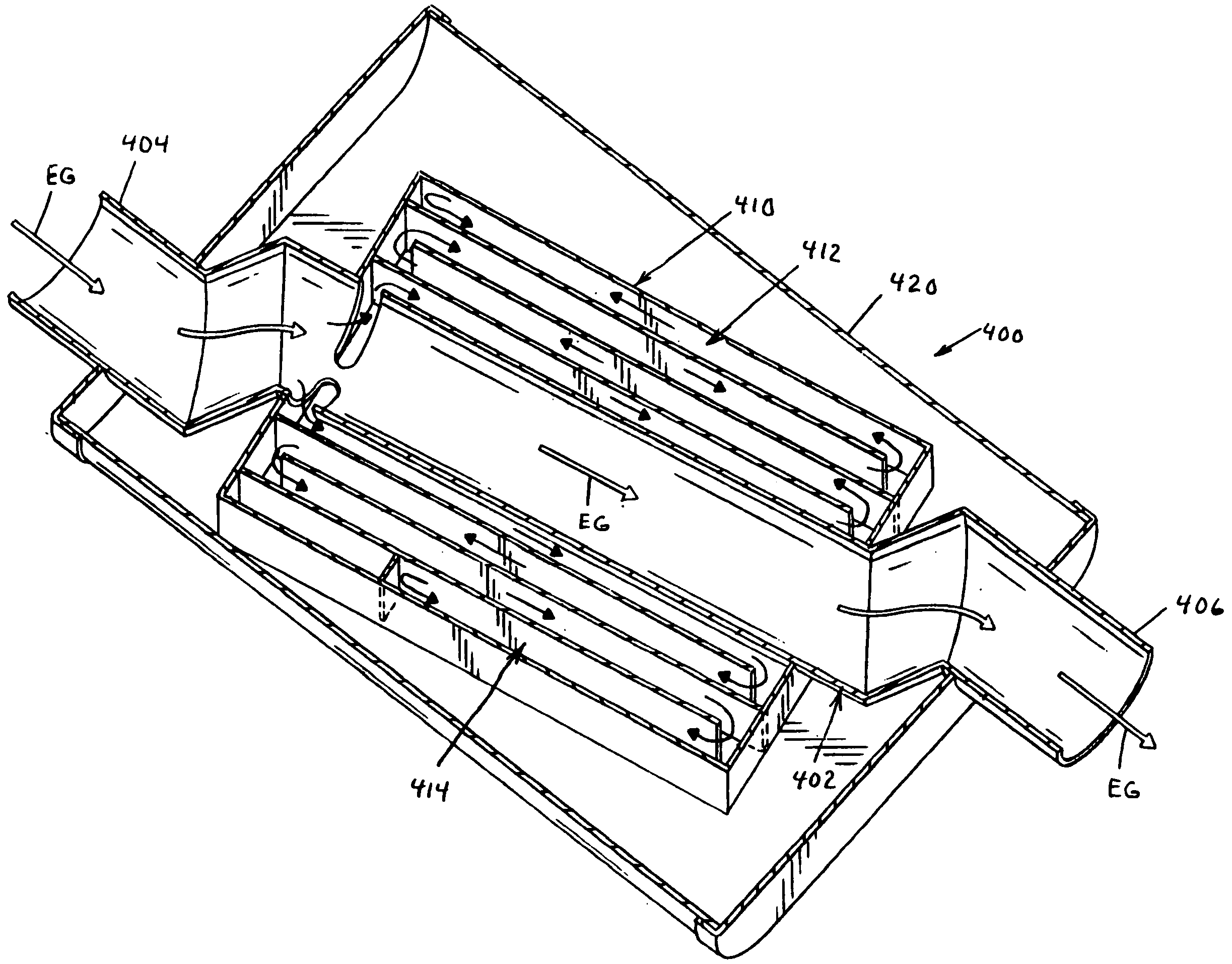
[0026]In accordance with the present invention, provided is a side branch type muffler which can be readily tuned to produce any desired sound in a subcompact and lightweight design allowing use in virtually all types of vehicles. More particularly, provided is a muffler design that is shorter in both overall height and overall length than prior art mufflers even though the same sound reflection is achieved.
[0027]In this respect, a muffler according to the present invention includes an elongated fluid passage extending between an inlet and an outlet such that the outlet is in fluid communication with the inlet. Further, the inlet can be configured to be connectable with the gases exhausted from the engine and the outlet configured to be in fluid connection atmosphere. The passage has a first side region and a second side region that is circumferentially spaced from the first region wherein a fluid passage is positioned in at least one of the first and second side regions. The muffler further includes a side attenuation sound chamber adjacent the at least one of the side regions such that the chamber is circumferentially spaced from the other of the at least one side region. This configuration produces a muffler that has a width that is greater than the height (or visa versa) such that the smaller height dimension allows use of this muffler in vehicles with certain size constraints.
[0028]A muffler according to another aspect of the present invention can include an elongated fluid passage with a first fluid passage in the first region and a second fluid passage in the second region. Further, the muffler can include a first side attenuation sound chamber adjacent the first region and in fluid connection with the first passage and a second side attenuation chamber adjacent the second region and in fluid connection with the second fluid passage. In this embodiment, the second chamber is circumferentially spaced from the first chamber wherein a greater range of sound can be attenuated without increasing the overall height or length of the muffler.

Problems solved by technology

Engine noise in an internal combustion engine typically is generated by the sudden expansion of combustion chamber exhaust gases.
As the wave front passes an object, an overpressure is created at the surface of the object, and it is this overpressure that is a direct cause of audible and objectionable noise.
However, from a practical standpoint, design criteria often dictate the size of the muffler which must be kept as small as possible.
However, these approaches are often accompanied by a substantial increase in the back pressure or resistance of the muffler to the free discharge of the combustion gasses.
The increase in backpressure can result in a decrease in the output horsepower of the engine with a resulting loss of efficiency in fuel economy.
The drawback to resonator mufflers is the large volume required to dampen low frequency sound waves.
However, low frequency sound waves which produce the most objectionable noise require long, side branch lengths which make it difficult to fit within the confines of certain automotive applications.
Specifically, a muffler could be tuned to a desired sound with the engine on a test stand, but produce objectionable resonance in the cabin.
However, the approach followed was random and haphazard and simply involved reconstructing entirely different side branch designs until one resulted in the removal of the objectionable noise.
Unfortunately, the length of the side branch typically exceeded the space limitations for the muffler design.
However, while the Huff muffler is effective, it is limited in its application due to the size of the radially spaced sound passages.
Further, additional sound chambers, to attenuate multiple frequencies, increase the length of the muffler wherein it can be too long for certain vehicles.
The Huff mufflers also can be costly to manufacture in that they require successively decreasing radial height for each successively larger diameter sound passages of the outer passages to avoid pressure undulations and accompanying sound wave variations as the waves travel in a sound path from one sound passage to another radially spaced sound passage.

Method used


Image

  • Muffler
  • Muffler
  • Muffler

Examples


Embodiment Construction

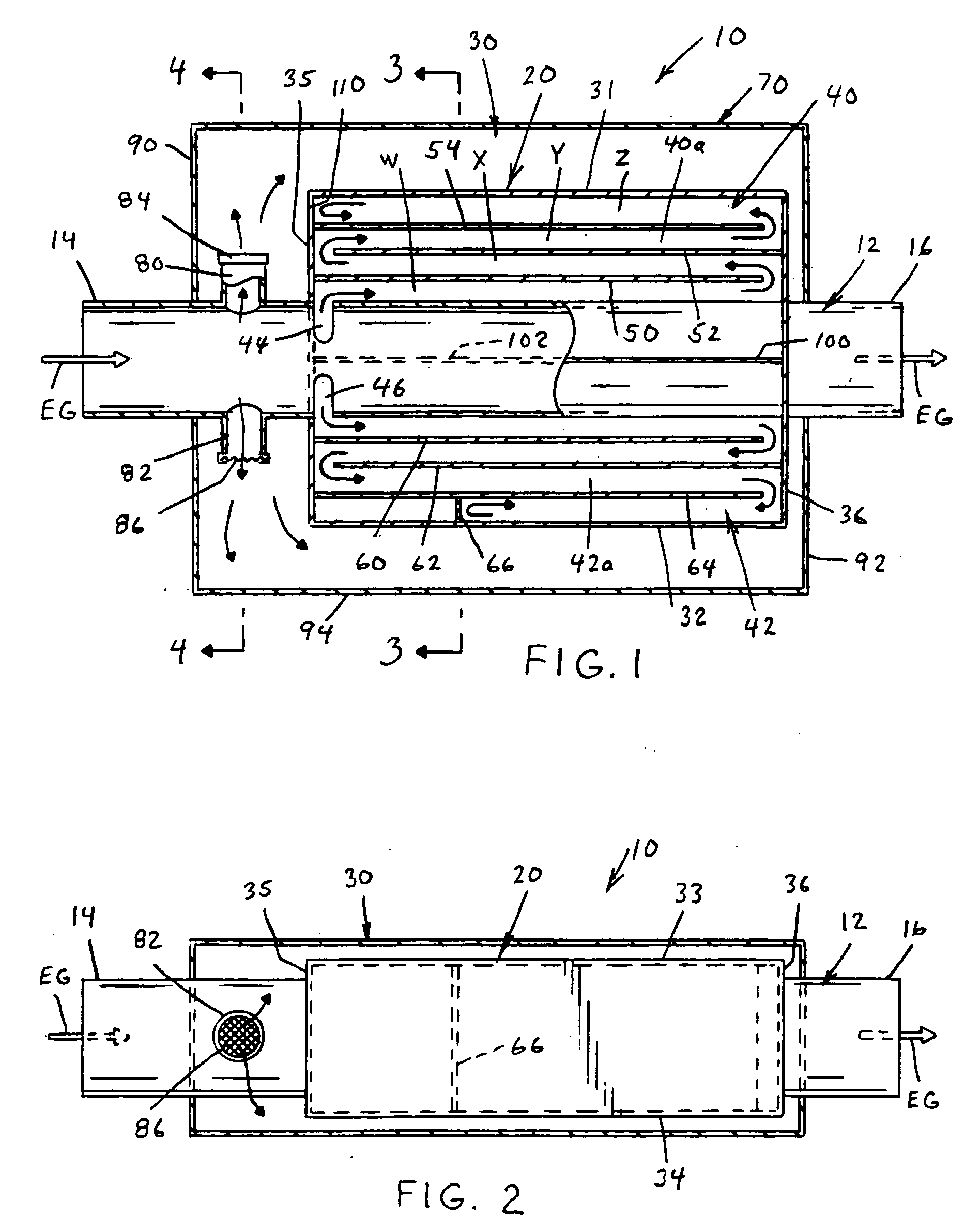
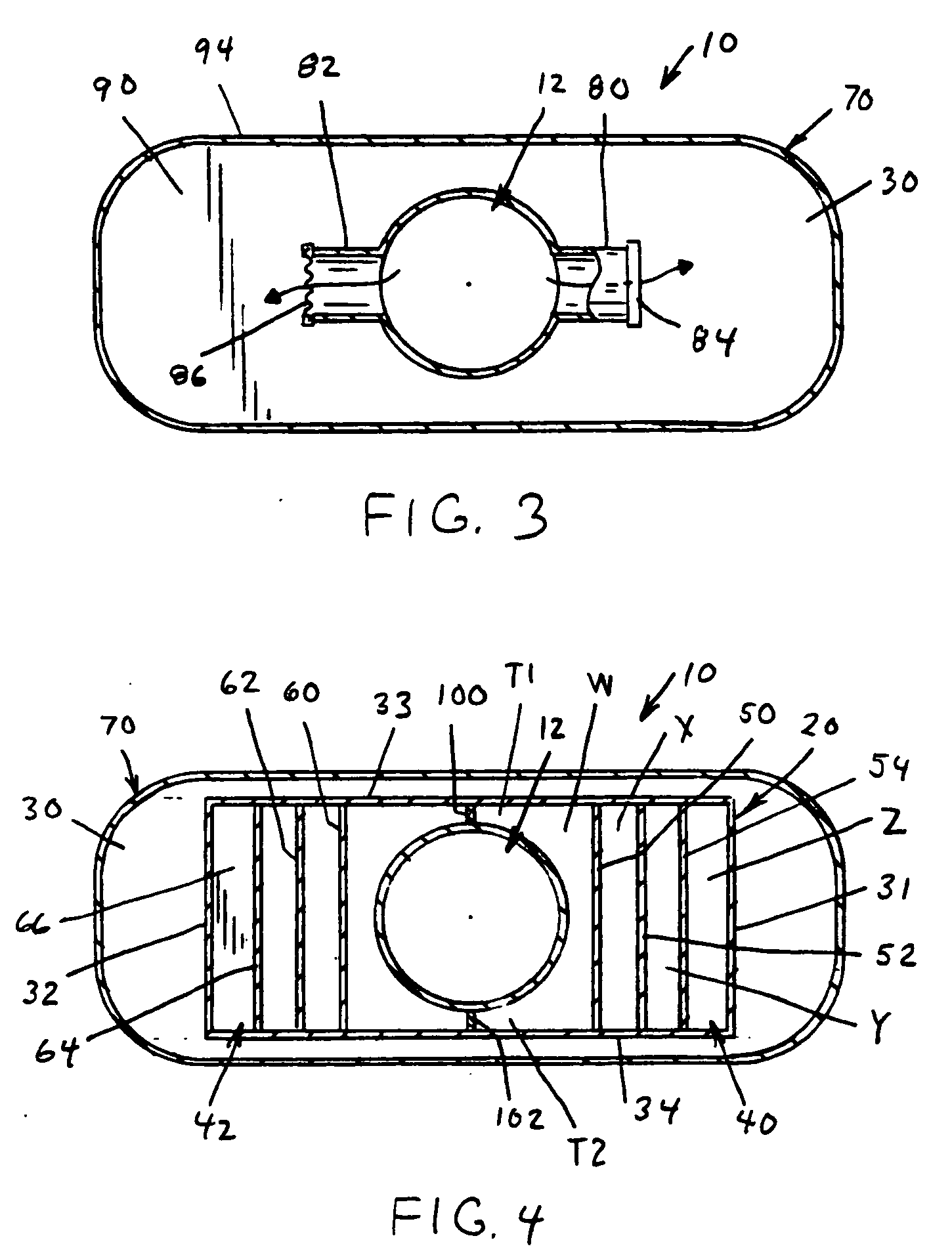
[0056]Referring now to the drawings wherein the showings are for the purpose of illustrating preferred and alternative embodiments of the invention only and not for the purpose of limiting same, there is shown in FIGS. 1-4 a muffler 10 illustrating at least one embodiment of the present invention.

[0057]Muffler 10 has an inner, axially extending through pipe or passage 12 which can be tubular, as is shown, and includes an inlet 14 and an outlet 16 wherein the exhaust of an internal combustion engine flows through muffler 10 from inlet 14 to outlet 16. Muffler 10 further includes an inner sound vessel 20 and an outer sound chamber 30. The arrows in FIG. 1, and in other Figures in this specification, generally show the flow of exhaust gases but, are illustrated in nature only in that they are intended to generally show the gas flow and / or sound pulse flow through the sound chambers at a given time and they do not show all flow patterns within muffler 10.

[0058]Turning to inner vessel 20...


PUM


Abstract

A muffler for reducing the sounds of combustion gases exhausted from an internal combustion engine. The muffler including an elongated fluid passage extending between an inlet and an outlet such that the outlet is in fluid communication with the inlet. The inlet of the muffler being connectable with the gases exhausted from the engine and the outlet being connectable with the atmosphere. The passage having a first side region and a second side region circumferentially spaced from the first region with a fluid passage in at least one of the first and second side regions. The muffler further including a side attenuation sound chamber adjacent the at least one of the side regions wherein the chamber is circumferentially spaced from the other of the at least one side region.

Description

[0001]This invention relates generally to mufflers of the sound modifying type used with internal combustion engines to attenuate engine noise and more particularly to mufflers conventionally referred to as side branch mufflers. This application claims priority in Provisional Patent Application Ser. No. 60 / 958,885 that was filed on Jul. 10, 2007 which is incorporated by reference herein.[0002]The invention is particularly applicable to and will be described with specific reference to a straight through muffler for use in sports cars or high performance automotive vehicles. However, as will be appreciated by those skilled in the art that the inventive concepts disclosed herein may be utilized for any number of muffler applications and in combination with or as part of other muffler systems or concepts for attenuating a specific or a specific range of sound waves.INCORPORATION BY REFERENCE[0003]The following patents are incorporated by reference as indicative of the muffler art so tha...

Claims


Application Information

Patent Timeline
Patent Type & Authority Applications(United States)
IPC IPC(8): F01N1/08
CPCF01N1/02F01N2490/155F01N2470/14
Inventor SKOWRONSKI, KEITHBOCKWICH, MARKHUFF, RONALD G.
Owner TMG PERFORMANCE PRODS
Why Eureka
Try Eureka