Shaft grounding thread structure of an electric motor

a technology of electric motors and grounding threads, applied in current collectors, dynamo-electric components, mechanical energy handling, etc., can solve the problems of gradual rise of contact resistance value, noise and bearing failure, etc., to maintain a permanent clean surface, stable contact resistance, and reduce the effect of carbon brush wear

Inactive Publication Date: 2009-01-15
CHI HUA FITNESS
View PDF6 Cites 15 Cited by
  • Summary
  • Abstract
  • Description
  • Claims
  • Application Information

AI Technical Summary

Benefits of technology

[0009]Therefore, it is a primary object of the present invention to provide a thread structure for the shaft grounding of an electric motor that includes a thin thread is formed on the surface of the slip ring or the shaft to replace the conventional face contact with the “linear contact” between the surface of the carbon brush and the thread head. During the rotation, the development of friction heat and the oxidation film will be substantially eliminated. Furthermore, the effect of spiral conveyor belt will be created when the thread rotates. This can remove the toner, copper powder, etc. produced by friction acting on the surface of the carbon brush and keep a permanent cleanness of the surface of the carbon brush. In this way, a stable contact resistance between the shaft (or the slip ring) and the carbon brush can be maintained and a long-term test shows that the wear of the carbon brush will be further reduced before improvement.

Problems solved by technology

Due to the corrosion of the electric arc, the crater-like corrosion spots and the corrosion spots stemming from washboard effect will be formed on the surface of the rolling way of the inner and outer rings 152, which result in noise and bearing failure.
It results in a gradual rise of the contact resistance value.

Method used


Image

  • Shaft grounding thread structure of an electric motor
  • Shaft grounding thread structure of an electric motor
  • Shaft grounding thread structure of an electric motor

Examples


first embodiment

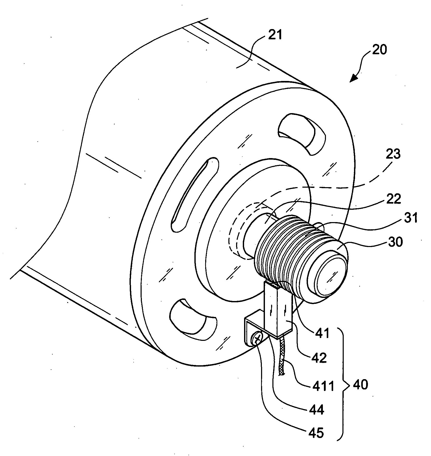
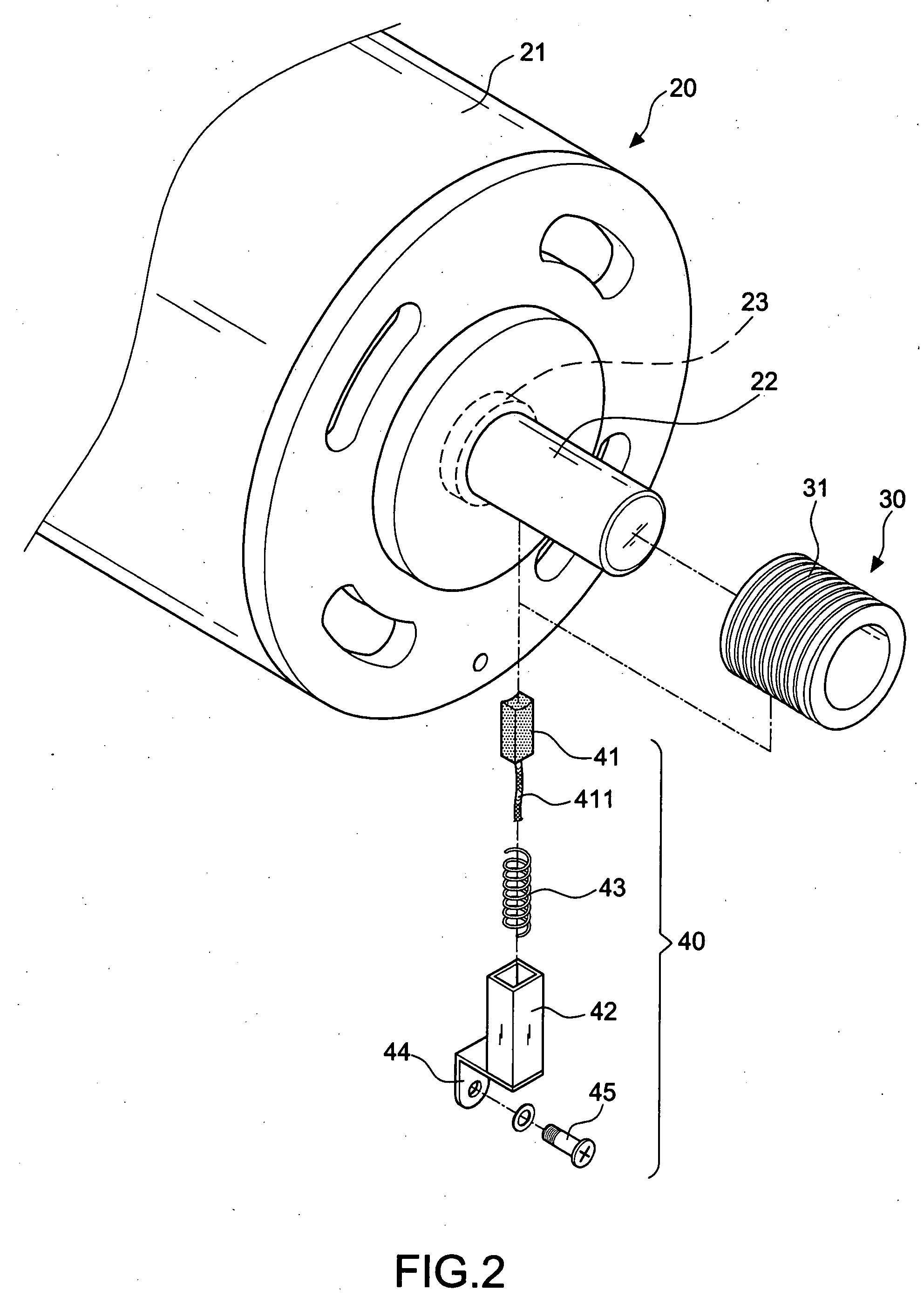
[0021]As shown in FIG. 2 and FIG. 3, a first embodiment according to the invention consists of an electric motor 20 and a grounding carbon brush device 40.

[0022]The electric motor 20 includes a housing 21. A rotary drivable shaft 22 is disposed within the housing 21 and supported by the ball bearing 23 outside of the housing 21. Since it belongs to the conventional technique of the electric motor, a further description won't be given hereinafter.

[0023]It is characterized that the end of the shaft 22 extends through the motor housing 21, on which a slip ring 30 is assembled. A thin thread structure 31 is formed on the circumferential surface in such a way that the surface of the tail of shaft 22 is provided with thin thread structure.

[0024]The grounding carbon brush device 40 is located on one side of the thin thread structure 31 and composed of a carbon brush 41, a hollow positioning body 42 for receiving the carbon brush 41 as well as a spring 43 positioned within the hollow body, ...

second embodiment

[0028]FIG. 6 shows schematically a second embodiment according to the invention, wherein the thin thread structure 31 is formed directly on the circumferential surface of the tail of the shaft 22 and has the identical function as the previous embodiment.


PUM


Abstract

Thread structure for the shaft grounding of an electric motor having a thin thread formed on the surface of the slip ring or the shaft to replace the conventional face contact with the “linear contact” between the surface of the carbon brush and the thread head. During the rotation, the development of friction heat and the oxidation film will be substantially eliminated. Furthermore, the effect of spiral conveyor belt is created when the thread rotates. This can remove the toner, copper powder, etc. produced by friction acting on the surface of the carbon brush and keep a permanent cleanness of the surface of the carbon brush. In this way, a stable contact resistance between the shaft (or the slip ring) and the carbon brush can be maintained and a long-term test shows that the wear of the carbon brush will be further reduced before improvement.

Description

BACKGROUND OF THE INVENTION[0001]1. Field of the Invention[0002]The invention relates to a shaft grounding thread structure of an electric motor, and more particularly to a shaft grounding structure in which a thin thread is formed on the surface of a slip ring or the shaft to replace the conventional face contact by the “linear contact” between the surface of the carbon brush and the thread peak.[0003]2. Description of the Related Art[0004]As shown in FIG. 1, a conventional electric motor consists of a housing 11, a stator 12, a rotor 13, a rotary drivable shaft 14 as well as a ball bearing 15 for supporting the shaft. As a result of the unbalance of magnetic circuit, external voltage (such as the PWM-voltage of the AC motor frequency inverter or DC motor speed controller), shaft magnetizing effect and the electrostatic induction (such as the electrostatic charging arising between pulley 16 and the belt 161) may generate a shaft voltage during the operation of this type of electric...

Claims


Application Information

Patent Timeline
Patent Type & Authority Applications(United States)
IPC IPC(8): H02K11/00H02K13/00
CPCH02K11/0089H02K11/40
Inventor HSIEH, LI-MIN
Owner CHI HUA FITNESS
Why Eureka
Try Eureka