Secondary side synchronous rectifier for resonant converter

a synchronous rectifier and converter technology, applied in the direction of dc-dc conversion, climate sustainability, power conversion systems, etc., can solve the problems of controller ics not being able to operate during burst mode conditions, unsatisfactory performance, and effective heat removal from sealed boxes, so as to reduce conduction and leakage losses

Inactive Publication Date: 2009-01-15
INFINEON TECH AMERICAS CORP
View PDF12 Cites 87 Cited by
  • Summary
  • Abstract
  • Description
  • Claims
  • Application Information

AI Technical Summary

Benefits of technology

[0024]It is another object of the present invention to reduce conduction and leakage losse

Problems solved by technology

In the case of external adapters/chargers, designed for portable electronic equipment, that are housed in completely sealed enclosures for safety reasons, effective heat removal from the sealed box poses a major design challenge since the system cooling now primarily relies only on natural convection and radiation.
Due to the complexity, cost, and unsatisfactory performance of the existing discrete/integrated solutions, output rectification in these converters has been widely implemented using diodes.
Apart from the fact that these control techniques are not suitable for synchronous rectification in resonant converters, these controller ICs cannot operate during burst mode conditions.
Further, as described in Reference 2, the complex operating modes of resonant converters do not allow self-driven gate-drive techniques or the use of primary gate signals to drive the secondary-side MOSFETs.
For conventional PWM converters, they can only be optimized at a lowest input voltage where the duty cycle reaches its maximum value and the efficiency drops at a high line where the duty cycle is much smaller.
Therefore, the wide range operation dramatically reduces the converter efficiency at the normal operating conditions and increases the thermal management requirements for the system.
As is known to those of skill in the art, the design is simple and requires no secondary side controller, but the forward conduction losses of the diodes are substantial, particularly when the output voltages are low.
Hence, control driven rectification cannot be implemente

Method used


Image

  • Secondary side synchronous rectifier for resonant converter
  • Secondary side synchronous rectifier for resonant converter
  • Secondary side synchronous rectifier for resonant converter

Examples


Embodiment Construction

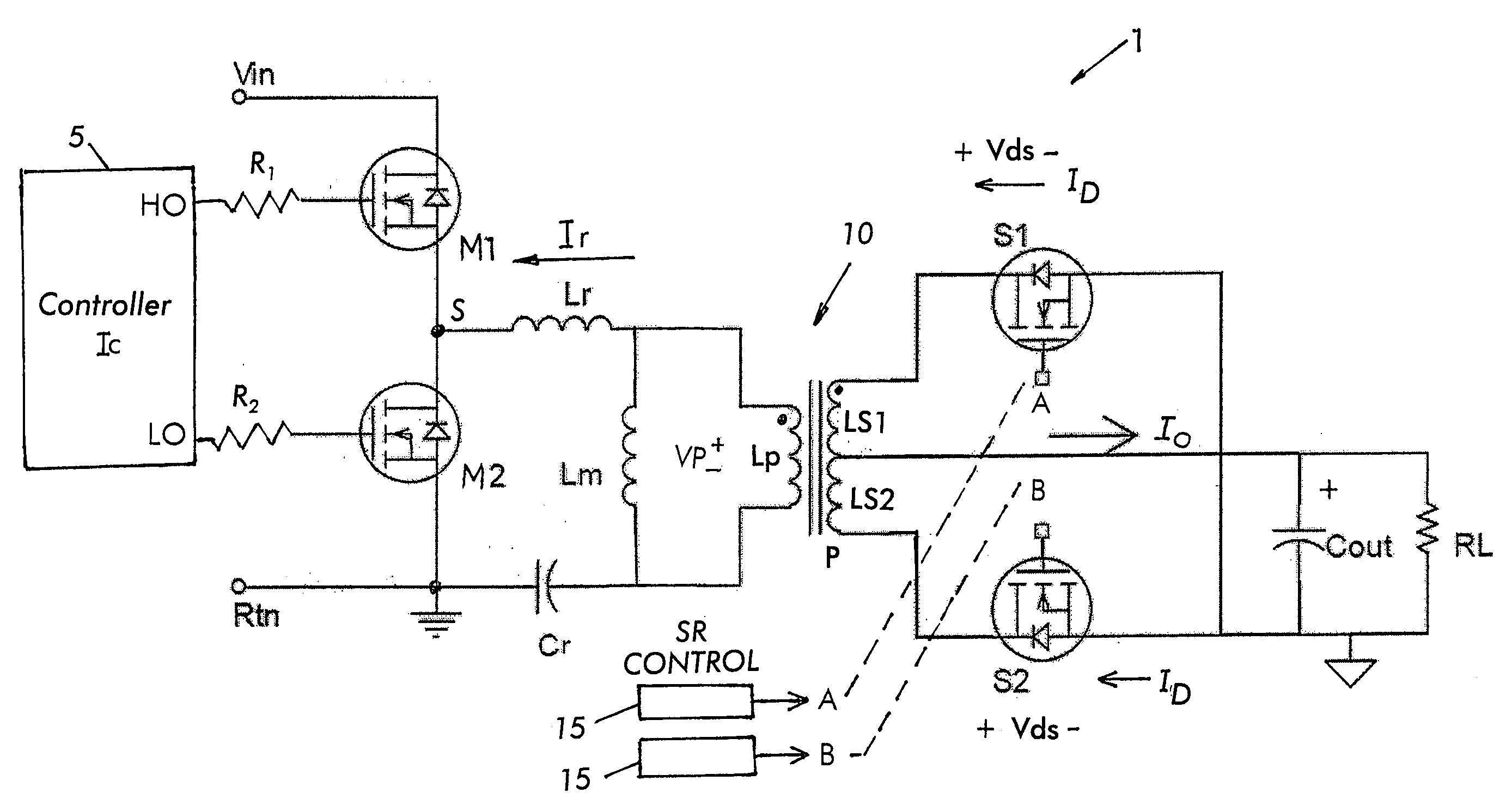
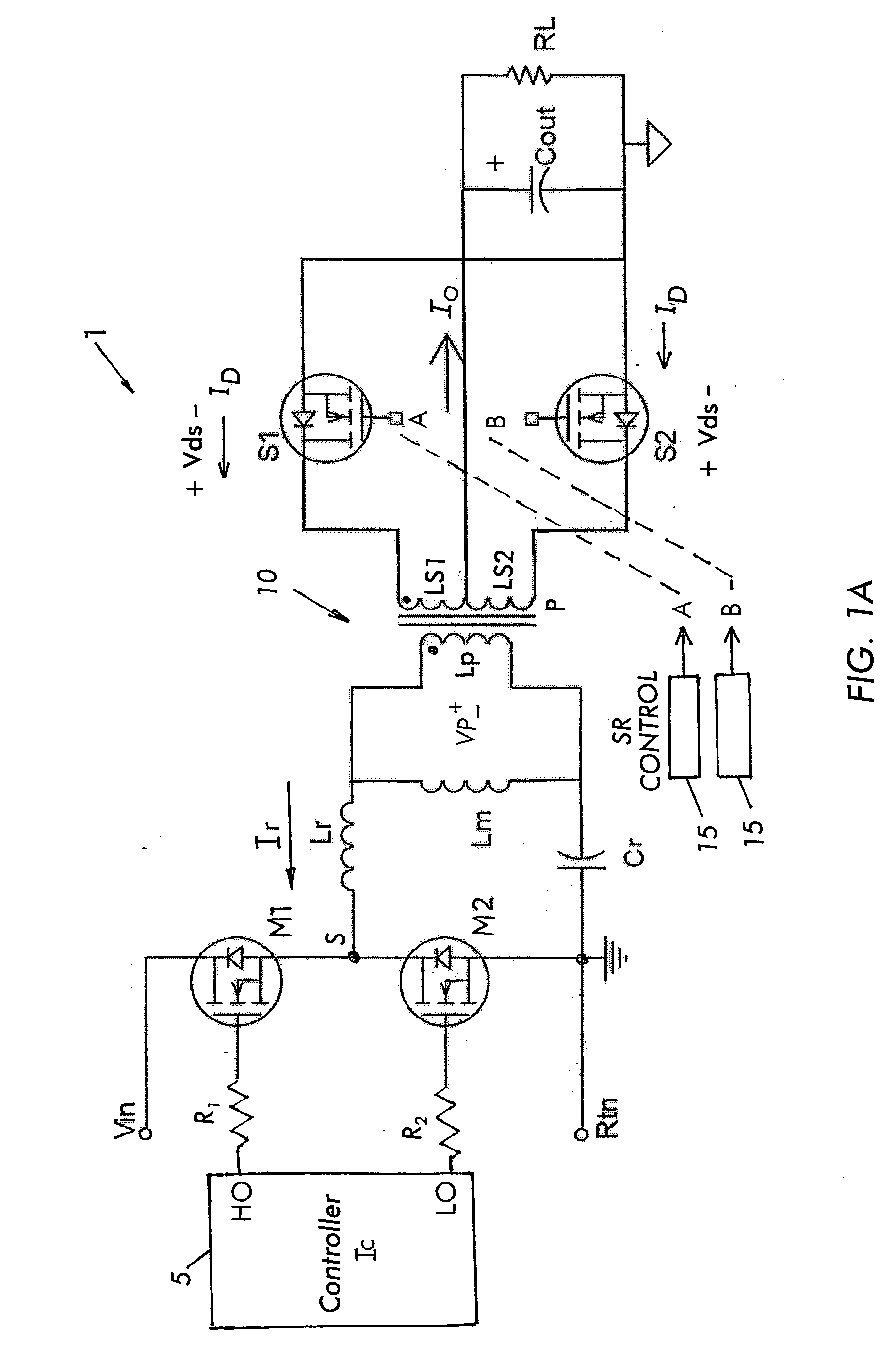
[0051]The present invention provides a solution for replacing diode rectifiers with synchronous rectification in resonant DC-DC converters independent of the topology and operating modes of the converter. This in turn dramatically reduces conduction and leakage losses.

[0052]To emulate the diode rectification function it is necessary to determine the direction of flow of current in the switch and turn off the switch promptly when the current direction reverses. To perform these functions, the current in the switch is sensed using the switch's on-state resistance. The invention switches the two synchronous MOSFETs S1 and S2 (FIG. 1a) ON and OFF depending on their sensed drain to source voltages (i.e., VDS1 and VDS2). This basic design is described in U.S. patent application Ser. No. 10 / 978,719 entitled “Integrated Synchronous Rectifier Package,” for a half-wave synchronous rectifier (IR-2636).

[0053]FIG. 5 illustrates an internal block diagram of an eight pin IC 15 designed to control ...


PUM


Abstract

A resonant converter including a primary side switching stage having high- and low-side switches series connected at a switching node and controlled by a primary side controller; a transformer having a primary coil and a secondary coil, the secondary coil having at least one pair of portions series connected at a node, a resonant tank formed by series connecting the primary coil to the switching node with a first inductor and a first capacitor; at least one pair of first and second secondary side switches connected to the at least one pair of portions, respectively, the first and second secondary side switches of each pair being used for synchronous rectification; and a secondary side controller to control and drive the first and second secondary side switches of each pair by sensing voltage across each secondary side switch and determining a turn ON and turn OFF transition for the first and second secondary side switches in close proximity to a point in time when there is zero current through the secondary side switch to achieve synchronous rectification.

Description

CROSS-REFERENCE TO RELATED APPLICATION[0001]This application is based on and claims priority to U.S. Provisional Patent Application Ser. No. 60 / 942,332, filed on Jun. 6, 2007 and entitled SMART RECTIFIER FOR RESONANT CONVERTER, and is a continuation-in-part of U.S. patent application Ser. No. 10 / 978,719, filed on Nov. 1, 2004 and entitled INTEGRATED SYNCHRONOUS RECTIFIER PACKAGE, which is based on and claims priority to U.S. Provisional Patent Application Ser. No. 60 / 517,333, filed on Nov. 4, 2003 and entitled INTEGRATED SMART RECTIFIER, the entire contents of which are hereby incorporated by reference.BACKGROUND OF THE INVENTION[0002]The present invention relates to secondary-side synchronous rectification in converters and more particularly to lessening conduction losses in rectifiers.[0003]The incremental demand for size and weight reduction of portable and on board power modules has spurred significant development and research efforts in high-density, low profile power supplies....

Claims


Application Information

Patent Timeline
IPC IPC(8): H02M3/335
CPCH02M3/33592Y02B70/1475Y02B70/1433Y02B70/10
Inventor SOLDANO, MARCOLOKHANDWALA, ADNAAN MUSTAFA
Owner INFINEON TECH AMERICAS CORP
Why Eureka
Try Eureka