Radio front end with resonant transmit/receive switch

a radio front end and switch technology, applied in the direction of transmission, electrical equipment, etc., can solve the problems of low breakdown voltage devices, circuits form parallel resonators or series resonators, and it is difficult and costly to integrate switches with transceivers or power amplifiers using low breakdown voltage devices

Active Publication Date: 2009-01-15
AXIOM MICRODEVICES
View PDF3 Cites 30 Cited by
  • Summary
  • Abstract
  • Description
  • Claims
  • Application Information

AI Technical Summary

Benefits of technology

[0006]In accordance with an exemplary embodiment of the present invention, a transceiver having a radio front end is provided. The radio front end includes an inductor having a first end and a second end. A capacitor having a first end and a second end is connected to the second end of the inductor. An antenna is connected to the second end of the inductor and the second end of the capacitor. A first switch is connected to the first end of the inductor and the first end of the capacitor, wherein the inductor and capacitor form a resonant circuit when the first switch is c

Problems solved by technology

One drawback of prior art resonant switching devices is that two resonators are used in a radio front end, one on a transmission path and the other on a receive path.
Another drawback is that the circuits form a parallel reso

Method used


Image

  • Radio front end with resonant transmit/receive switch
  • Radio front end with resonant transmit/receive switch
  • Radio front end with resonant transmit/receive switch

Examples


Embodiment Construction

[0012]In the description that follows, like parts are marked throughout the specification and drawings with the same reference numerals. The drawing figures might not be to scale and certain components can be shown in generalized or schematic form and identified by commercial designations in the interest of clarity and conciseness.

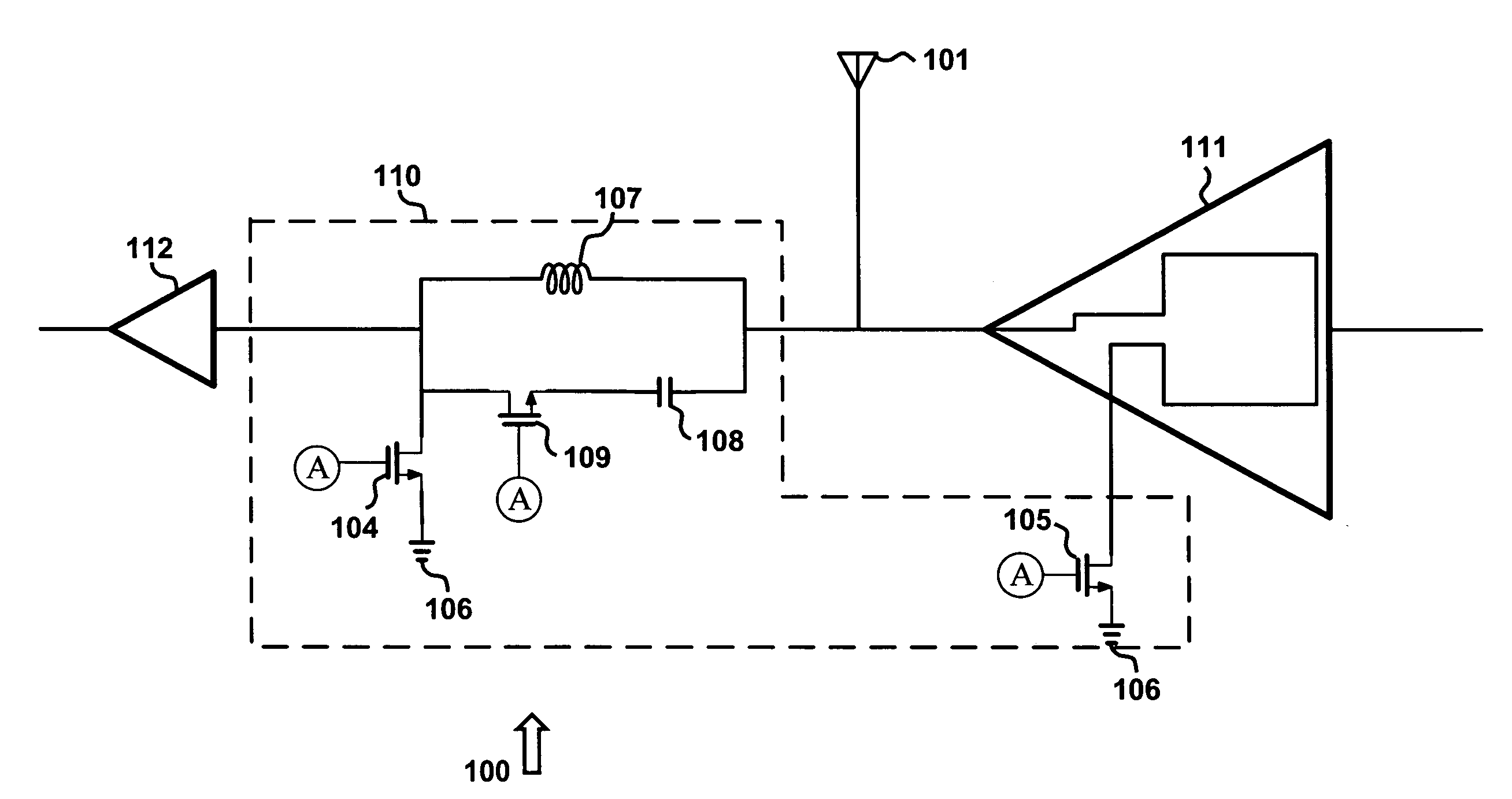
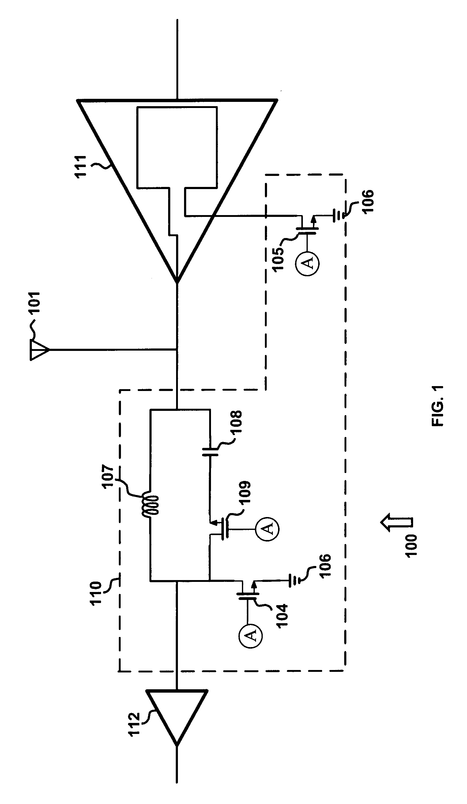
[0013]FIG. 1 is a diagram of radio front end 100 in accordance with an exemplary embodiment of the present invention. Radio front end 100 can be implemented in silicon, gallium arsenide, or other suitable materials, and can be implemented using complementary metal-oxide semiconductor (CMOS) processes or other suitable processes. Radio front end 100 utilizes a resonant switch to control the transmission or reception of a signal from an antenna.

[0014]Radio front end 100 includes resonant switch 116, which is disposed between a transmitter power amplifier 120 and a receiver low noise amplifier 118, and which controls transmission of the signal from antenna 10...


PUM


Abstract

A device having a radio front end is provided. The radio front end includes an inductor having a first end and a second end. A capacitor having a first end and a second end is connected to the second end of the inductor. An antenna is connected to the second end of the inductor and the second end of the capacitor. A first switch is connected to the first end of the inductor and the first end of the capacitor, wherein the inductor and capacitor form a resonant circuit when the first switch is closed. A second switch is connected to the resonant circuit, the second switch connecting the resonant circuit to ground through a low impedance when the first switch is closed. A third switch is connected to a transmit power amplifier connecting the transmit power amplifier to ground through a low impedance when the first switch is closed.

Description

BACKGROUND OF THE INVENTION[0001]Resonant switches for use as transmit-receive switches in radio front ends, such as those found in devices for wirelessly transmitting and receiving data, are known in the art. One drawback of prior art resonant switching devices is that two resonators are used in a radio front end, one on a transmission path and the other on a receive path. Another drawback is that the circuits form a parallel resonator or series resonator depending on the state of the switch. The use of two resonators can occupy more semiconductor surface area or more discrete components.[0002]The resonant switch is required to handle high voltage coming from the power amplifier. In some applications, such as cellular phone radios, this voltage can be greater than 10V. Prior art switches to handle such high voltages are implemented by semiconductor devices with high breakdown voltages. Other components in the radio, such as transceivers, are typically implemented using different se...

Claims


Application Information

Patent Timeline
IPC IPC(8): H04B1/44
CPCH04B1/44
Inventor QIAO, DONGJAINGKEE, SCOTT D.AOKI, ICHIROMCCLYMONT, DONALD
Owner AXIOM MICRODEVICES
Why Eureka
Try Eureka