

Stents
- Summary
- Abstract
- Description
- Claims
- Application Information
AI Technical Summary
Benefits of technology
Problems solved by technology
Method used
Image

Examples
example 1
PLLA Nanofiber Scaffold Preparation
[0289]Biodegradable poly(L-lactide) (PLLA) (Lactel Absorbable Polymers, Pelham, Ala., 1.09 dL / g inherent viscosity) was used to fabricate nanofiber scaffolds by electrospinning. (Zong, X., Biomacromolecules, 4(2): 416-23 (2003)). Briefly, the PLLA solution (10% w / v in chloroform) was delivered by a programmable pump to the exit hole of the electrode at a flow rate of 25 μL / minute. A high-voltage supply (Glassman High Voltage Inc., High Bridge, N.J.) was used to apply the voltage at 20 kV. The collecting plate was on a rotating drum that was grounded and controlled by a stepping motor. To align the nanofibers, the electrospun scaffold was stretched uniaxially to 200% engineering strain at 60° C. Nanofibrous scaffolds were approximately 150 μm in thickness. The surface of the nanofibrous scaffold was coated with 2% gelatin or fibronectin (5 μg / cm2) before cell seeding. No significant difference in cell adhesion and morphology was detected between gel...
example 2
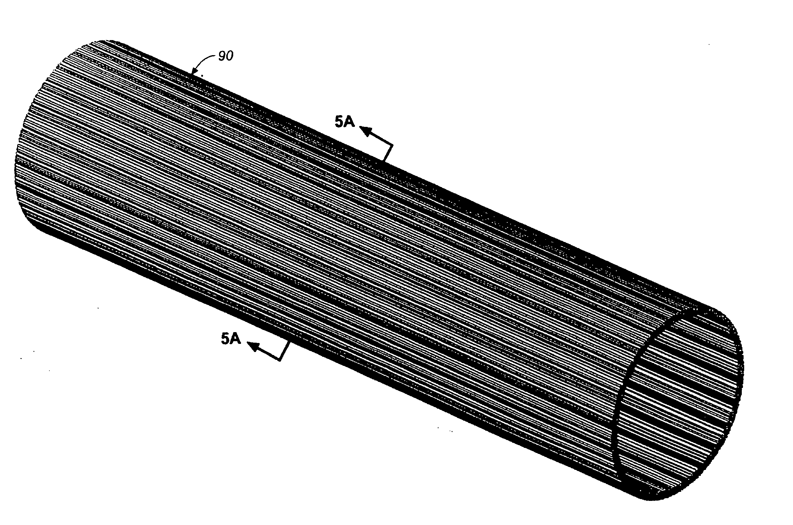
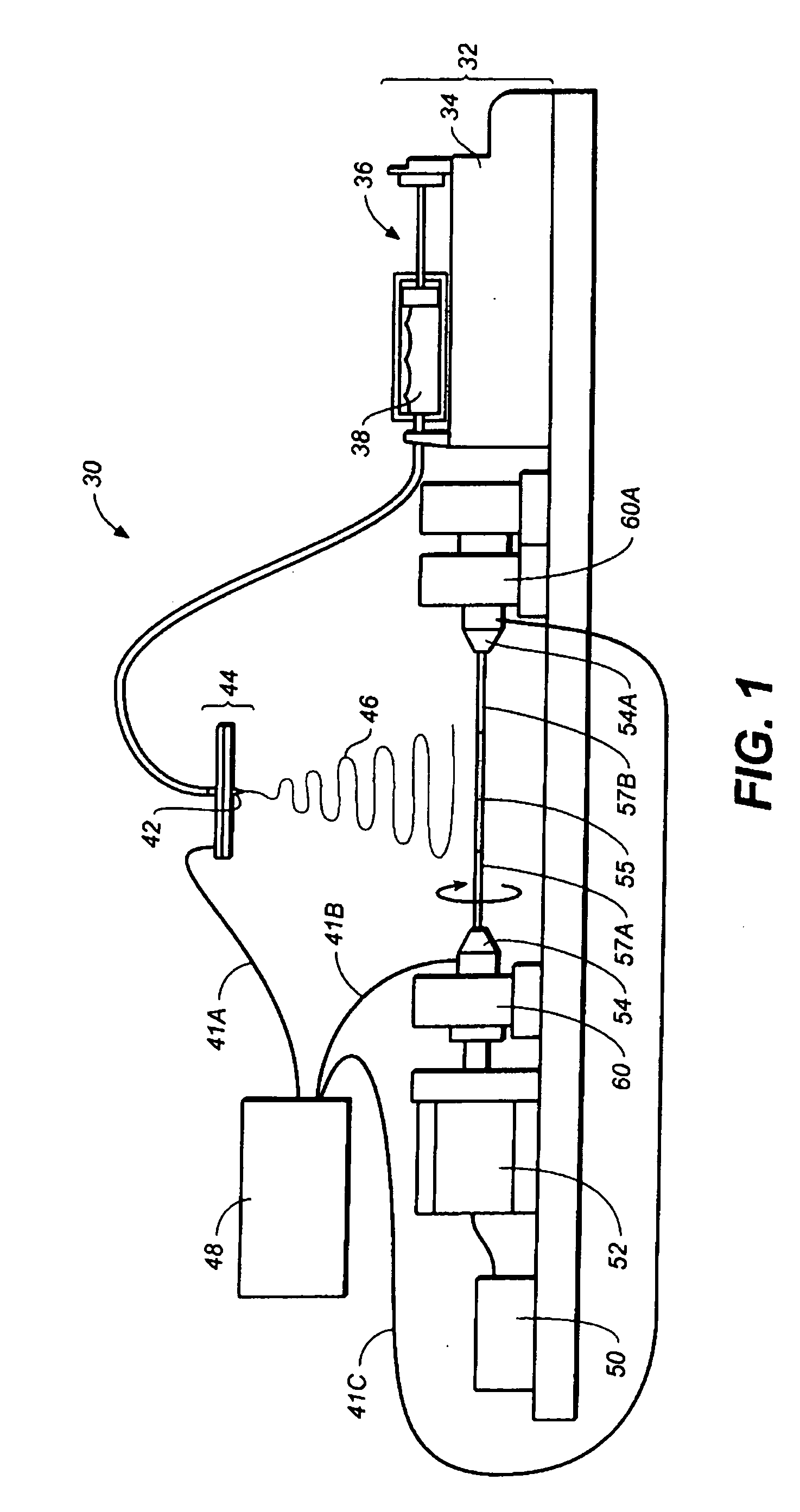
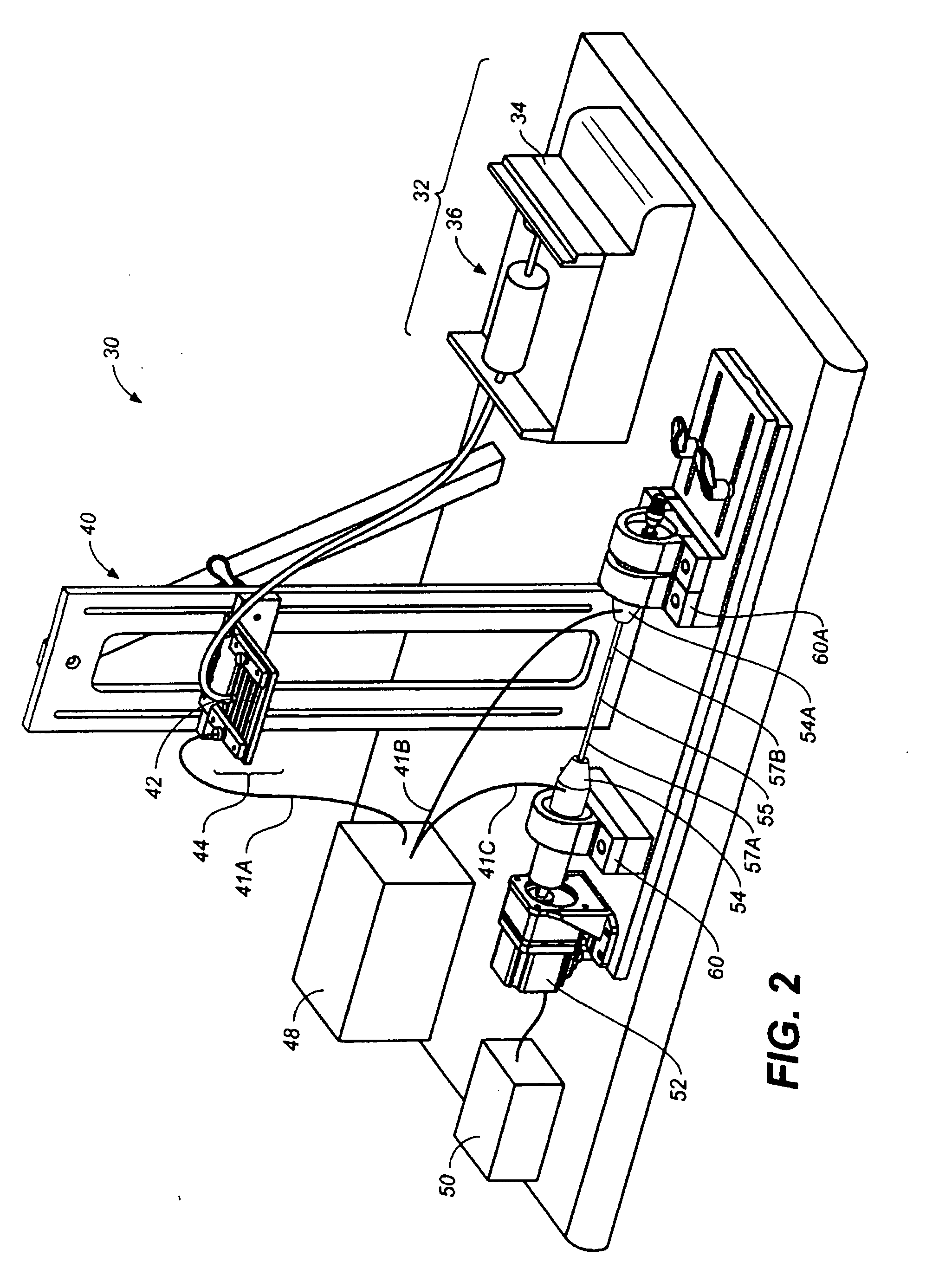
Longitudinally Aligned Polymer Scaffold Conduit
[0291]Biodegradable poly(lactic-co-glycolic-acid) (PLGA) (Lactel Absorbable Polymers, Pelham, Ala., 0.82 dL / g inherent viscosity) was used to fabricate nanofiber scaffolds by electrospinning. The PLGA solution (20% w / v in HFIP) was delivered by a programmable syringe pump to the exit hole of the electrode at a flow rate of 1 mL / hour. A high-voltage supply was used to apply the voltage at 11 kV. The collector substrate was a grounded steel mandrel attached to a motor capable of rotated the mandrel around its long axis. Teflon tape was wrapped around a section of the mandrel to create a non-conducting region. The mandrel was rotated at a slow speed (<15 rpm) as the PLGA fibers were electrospun. The jet alternated between the two sections of the mandrel separated by the non-conducting Teflon tape region resulting in deposition of PLGA fibers that were aligned parallel to the long axis of the mandrel. The rotation of the mandrel ensured eve...
PUM
| Property | Measurement | Unit |
|---|---|---|
| Angle | aaaaa | aaaaa |
| Angle | aaaaa | aaaaa |
| Angle | aaaaa | aaaaa |
Abstract
Description
Claims
Application Information