[0013]According to the invention, one or more improvements in alignment for a
polymer scaffold are included in the crimping process as in, according to one embodiment, a pre-
crimp process. Preparation for the pre-
crimp process includes a deionizing step to remove static buildup on the
polymer scaffold. By removing a static charge on the polymer material, the scaffold should sit more level on the support, i.e., a rod, mandrel or
catheter, thereby improving alignment with the crimper. Additional measure may be employed. A
carriage support for positioning the scaffold within the crimper includes a magnetic element for engagement with an end of the support holding the scaffold. The scaffold support is held to a surface of the base e.g., a grooved channel proximal to, or formed by the magnetic element, by a
magnet force of attraction. When the surface of the base is aligned with the crimper, so too will the support align with the crimper. Less operator skill is required to align the scaffold. Slight misalignments causing damage when the
polymer scaffold is crimped are, therefore, more often avoided. Existing devices for scaffold alignment, by contrast, use
mechanical devices, e.g. lock knobs, that require adjustment, which can lead to more frequent misalignment problems.
[0014]A first and second
carriage support may be used to support both ends, as opposed to only one end of the scaffold support. In this alternative embodiment, the two ends of the scaffold support are supported by contacting surfaces of the respective bases of the carriage supports and held thereto by a
magnet force of attraction. Each base support is located on opposite ends of the crimper. Alternatively, only one of the bases may employ a
magnet. The second base is provided so that the free end of the scaffold support may be supported in addition to the fixed end to provide better accuracy in alignment. The second base may provide a flat
surface level with the surface of the first base
support surface, or each may have grooves to receive the ends of the scaffold support, in precise alignment with the central axis of the crimper. This arrangement may further reduce requirements for operator skill when aligning the stent with the crimper, e.g., the operator need only place the ends of the scaffold support within the aligned grooves.
[0015]Supporting both ends of the scaffold also permits it to support more weight without deflecting, which causes misalignment. A scaffold support, supported by two movable rails preferably as fixed (i.e., 6 degree of freedom restraint at both ends), may also be used to perform a pre-crimping process for two stents. A first and second carriage, which move left to right or
right to left along rails in
unison, each support a scaffold on opposite sides of the crimper. In this arrangement a stent on one side of the crimper may be pre-crimped first, followed by the stent on the opposite side. Alternatively, stents may be disposed on the improved support so that two or more scaffolds may be crimped simultaneously. This increases production efficiency for a pre-
crimp.
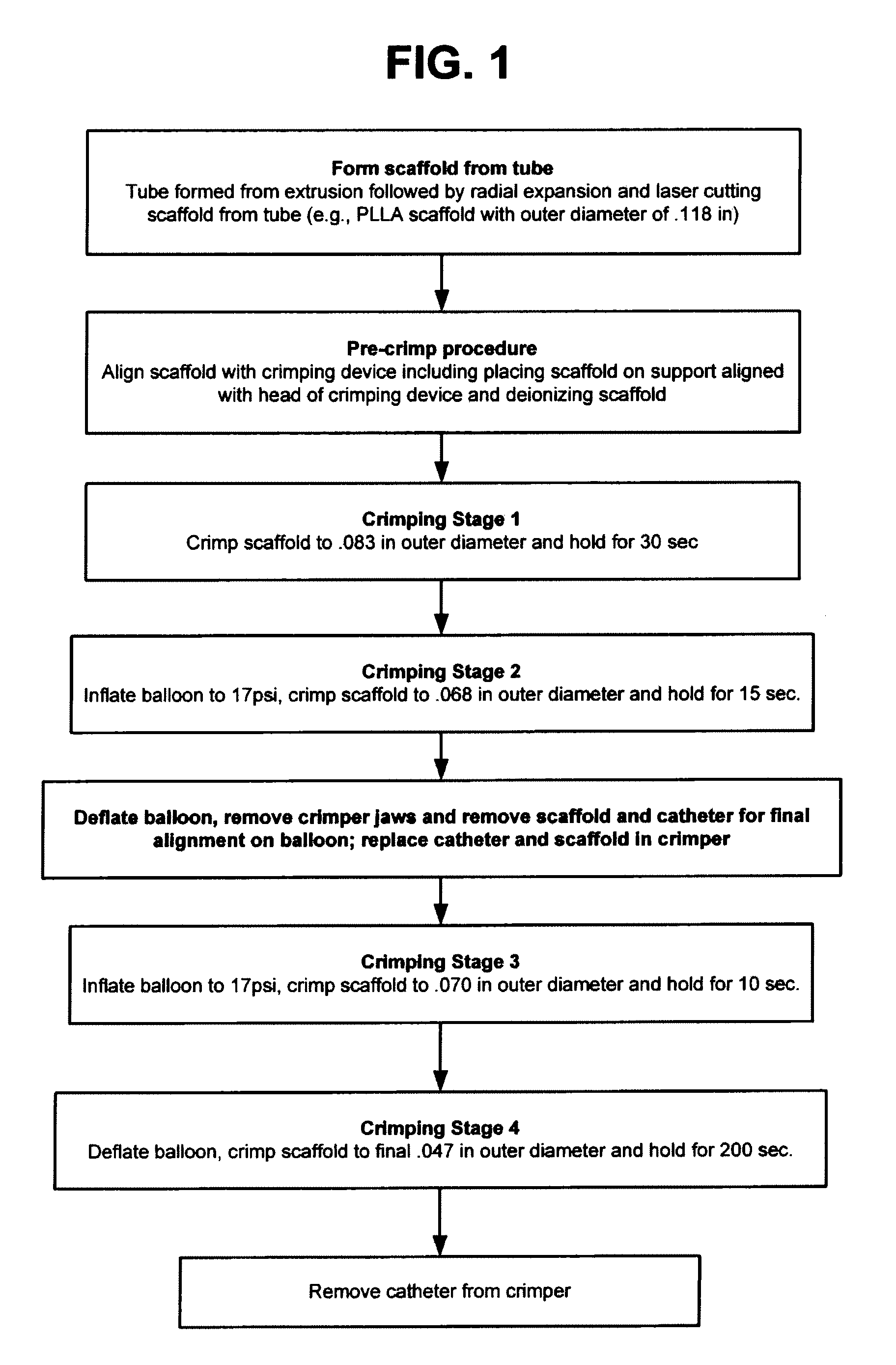
[0016]After being more suitably aligned, the polymer scaffold may be inserted into the crimper to reduce its
diameter to a pre-crimp
diameter. The reduced-diameter scaffold is then removed from the scaffold support, placed on, and aligned with the balloon of the delivery
catheter. The scaffold is then crimped to a final crimped diameter on the balloon. Preferably, a multi-step final crimping process includes heating the scaffold to a temperature just below the
glass transition temperature of the polymer to avoid damaging the scaffold when it is crimped and without significantly altering the scaffold's deployed strength / stiffness characteristics.
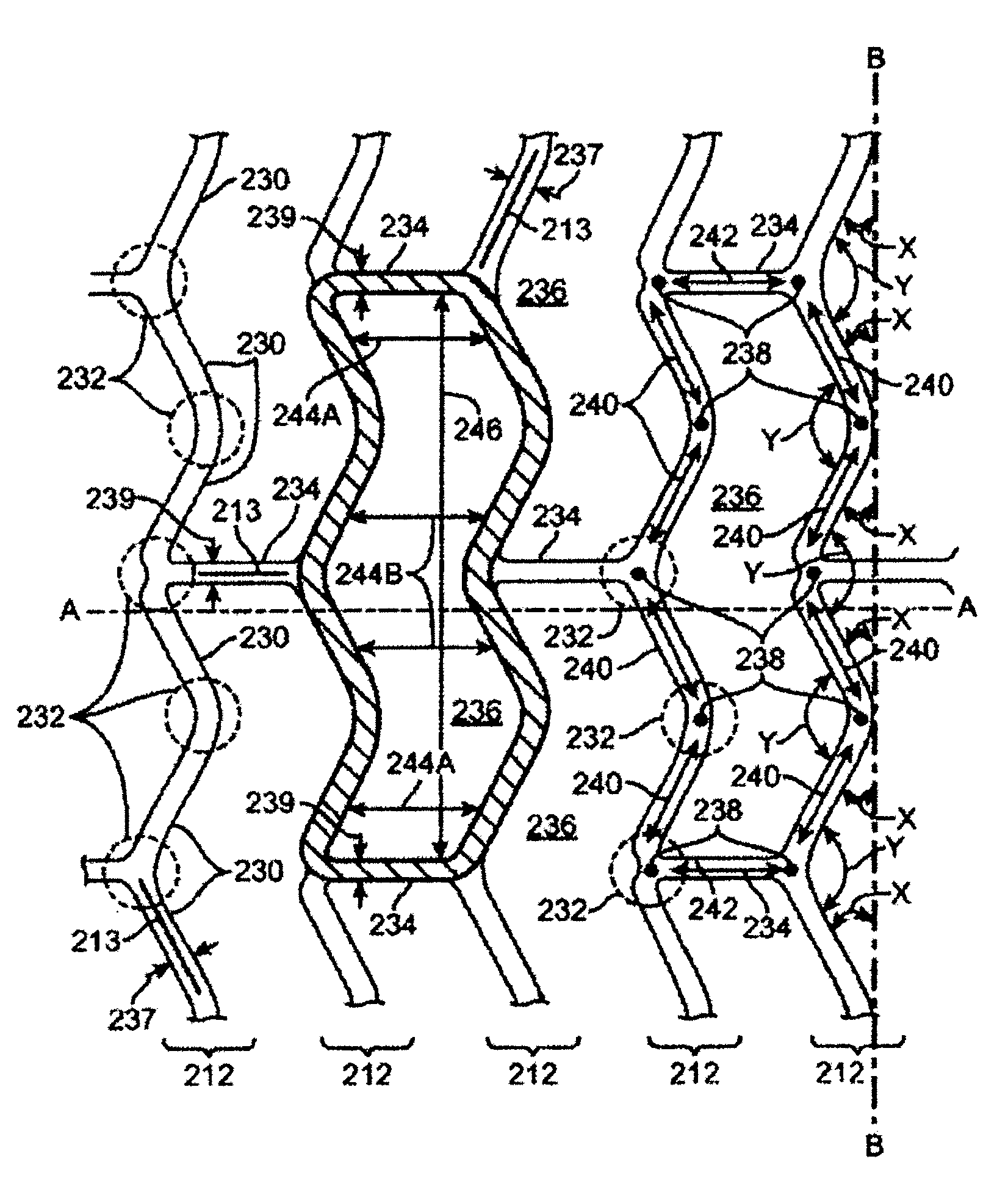
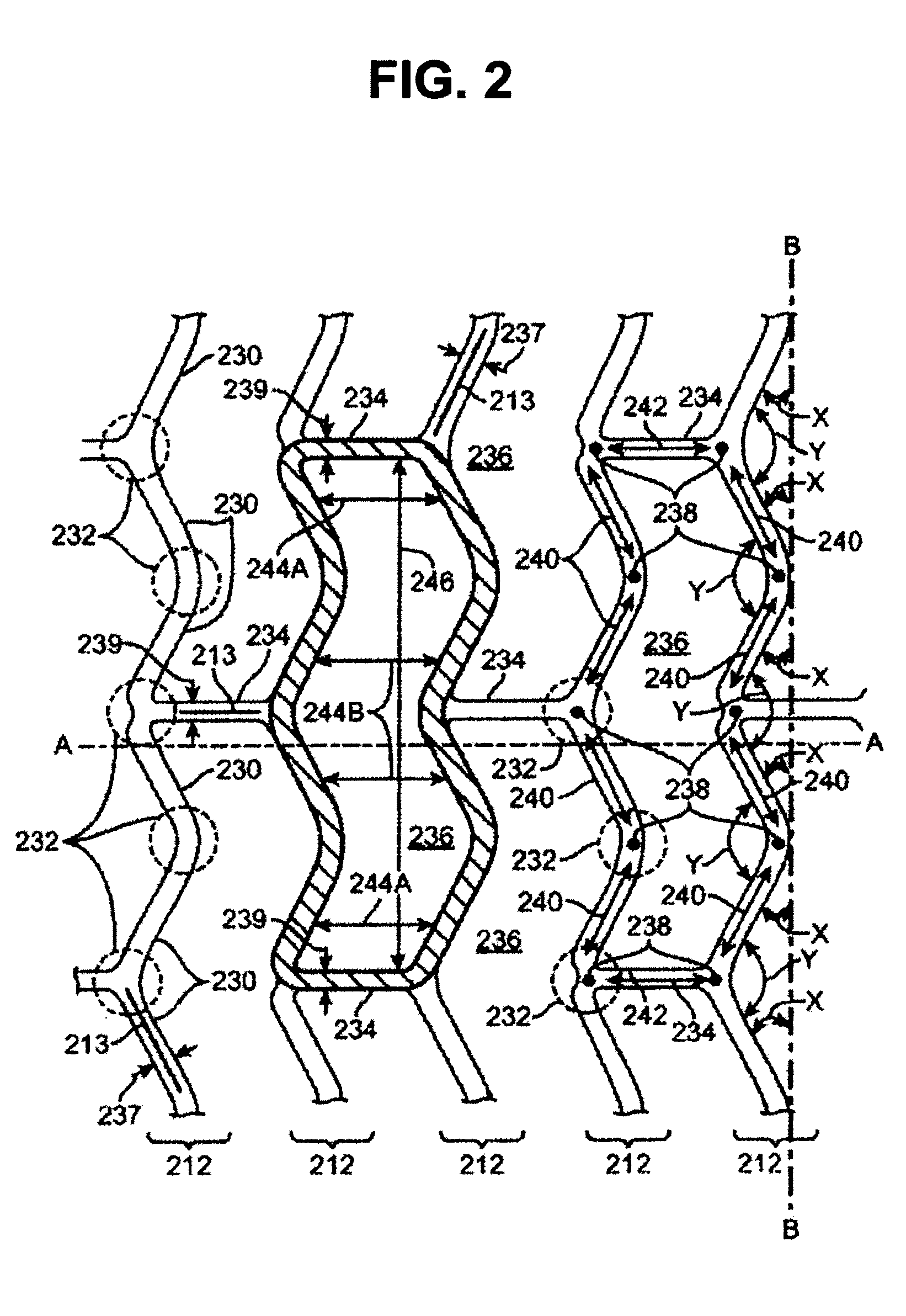
[0017]In one aspect of the invention there is a method for crimping a balloon-expanded stent scaffold to a balloon, comprising the steps of providing a tube; radially expanding the tube to increase its radial strength; forming the scaffold from the radially-expanded tube, including the steps of forming a circumferential series of closed cells having a W-shape and linear link struts connecting the W-shape cells. The scaffold is deionized and then the deionized scaffold is crimped to the balloon. Preferably the scaffold is deionized just prior to being inserted into the crimper to avoid damage to the scaffold when crimped.

