Position Sensing Device And Method

Active Publication Date: 2009-01-15
ALPINE ELECTRONICS INC
View PDF20 Cites 69 Cited by
  • Summary
  • Abstract
  • Description
  • Claims
  • Application Information

AI Technical Summary

Benefits of technology

[0028]According to some embodiments of the present invention, a reliability of each component of GPS output data is determined, and the degree of contribution of a component determined to be an unreliable component to correction processing is set to zero or almost zero, so a positioning accuracy can be increased.
[0029]According to some embodiments of the present invention, a reliability of each component of GPS output data is determined, and an error index of a component determined to be a reliable component is calculated to reduce the degree of contribution to the correction processing in accordance with the error index to thereby increase a positioning accuracy.
[0030]According to some embodiments of the present invention, even if a GPS receiver not outputting an error index is used, it is possible to determine a reliability of GPS measurement data (positional data and speed data in three directions, vehicle's latitude, longitude, and height) as well as calculate an error index of a component determined to be a reliable component. Thus, correction processing can be executed with a Kalman filter without requiring an expensive GPS receiver.
[0031]According t

Problems solved by technology

However, output data (position, orientation, speed vehicle, etc.) of the dead reckoning sensor includes an error in sensor measurement, so some error will occur.
In particular, position and orientation are calculated by integrating an output value of the sensor, so an error is cumulatively increased.
However, dead reckoning has a problem that an error in dead reckoning cumulatively increases due to an error in sensor output value and sensor mounting angle when no GPS data is received, which deteriorates an output accuracy.
In particular, a GPS signal cannot reach the navigation system in a vehicle in a multilevel parking structure or basement car park, and a positional error of about 100 m or less occ

Method used


Image

  • Position Sensing Device And Method
  • Position Sensing Device And Method
  • Position Sensing Device And Method

Examples


Embodiment Construction

(A) Summary of the Invention

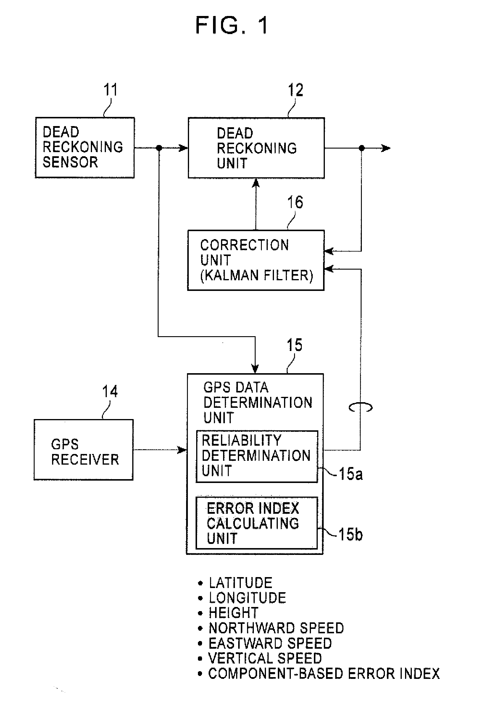
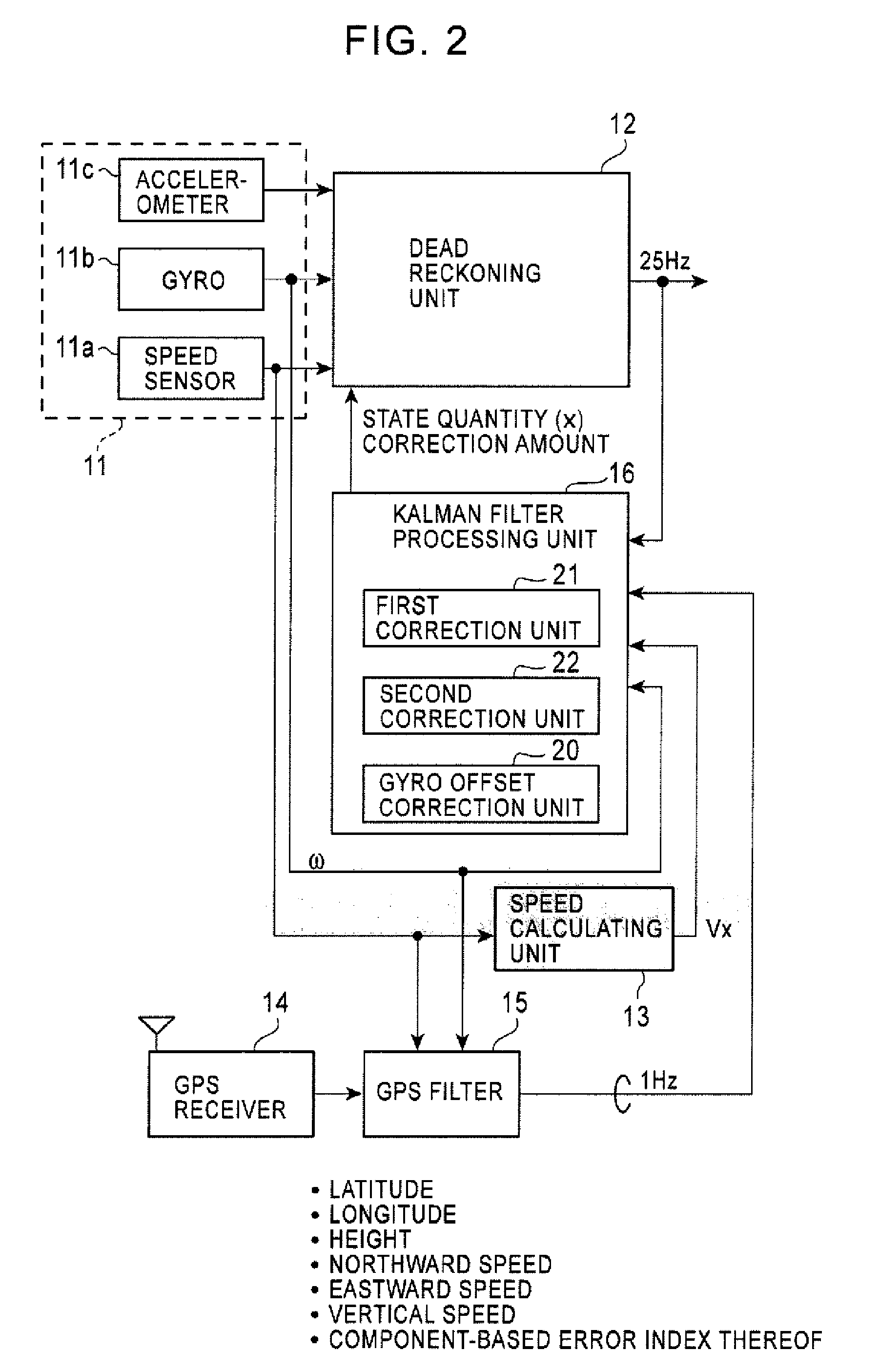
[0060]FIG. 1 is an explanatory view of a position sensing device according to the present invention. The device includes a dead reckoning sensor 11, a dead reckoning unit 12, a GPS receiver 14, a GPS data determination unit (GPS filter) 15, and a correction unit (Kalman filter processing unit) 16. The dead reckoning sensor 11 includes a moving distance detection unit (vehicle sensor) for measuring a moving distance of a vehicle, a relative direction sensor (gyro) for outputting a signal corresponding to an amount of change in vehicle direction, and an acceleration sensor for detecting an acceleration of a vehicle. The dead reckoning unit 12 calculates a vehicle position through dead reckoning at a predetermined cycle using an output signal of the dead reckoning sensor. The GPS receiver 14 calculates a three-dimensional position (latitude, longitude, and height) and three-dimensional speed (northward speed, eastward speed, and vertical speed) based on sign...


PUM


Abstract

A position sensing device and method are provided for executing correction processing based on a reliability and error index of each component of GPS output data to increase positioning accuracy. Correction processing is performed to correct a position determination result obtained through dead reckoning, and a vehicle speed, a pitch angle, and a sensor mounting angle used in position determination executed through dead reckoning in a measurement period of GPS in accordance with direction-specific positional components and speed components of a vehicle, which are measured with GPS to determine a reliability of each of the direction-specific positional components and speed components of the vehicle and calculate an error index of a component determined to be a reliable component, to set the degree of contribution of a measurement component determined to be unreliable to correction processing to zero or almost zero, and to reduce the degree of contribution of a measurement component determined to be reliable to correction processing in accordance with a value of the error index.

Description

BACKGROUND OF THE INVENTION[0001]1. Related Application[0002]The present application claims priority to Japanese Patent Application Number 2007-182818, filed Jul. 12, 2007, the entirety of which is hereby incorporated by reference[0003]2. Field of the Invention[0004]The present invention relates to a position sensing device and method for detecting a current position of a vehicle, and more specifically to a position sensing device and method capable of increasing the accuracy of a dead reckoning position.[0005]3. Description of the Related Art[0006]An in-vehicle navigating system employs both dead reckoning with a dead reckoning sensor and GPS (global positioning system) navigation with a GPS receiver.[0007]Dead reckoning is a technique of detecting a vehicles position, orientation, and speed using an output of an acceleration sensor for detecting an acceleration of a vehicle, a relative direction sensor (gyro, etc.) for detecting a change in vehicle direction, and a distance sensor...

Claims


Application Information

Patent Timeline
IPC IPC(8): G01C21/00G01S19/49G08G1/0969G09B29/10
CPCG01C21/165G01S19/47G01C25/005
Inventor WATANABE, TAKAYUKIHOSHIZAKI, TAKAYUKI
Owner ALPINE ELECTRONICS INC
Why Eureka
Try Eureka