Supercharge Your Innovation With Domain-Expert AI Agents!

Speech coding

a speech encoder and audio coding technology, applied in the field of speech encoders, can solve the problems of lossy coding being chosen, rapid degradation of quality, and high computational load of speech encoders, and achieve the effect of reducing computational load in speech encoders

Inactive Publication Date: 2009-01-15
NOKIA SOLUTIONS & NETWORKS OY
View PDF13 Cites 9 Cited by
  • Summary
  • Abstract
  • Description
  • Claims
  • Application Information

AI Technical Summary

Benefits of technology

The patent proposes a method for encoding an audio signal by transforming it into a sequence of frames, each frame comprising a plurality of coefficients. An optimisation function is applied to calculate test values for a set of pulses that represent the coefficients. The test values are compared with a selectability criterion to select a set of pulses that meet the criterion. The selected set of pulses is used to calculate an amplitude value for the frame. The technical effect of this method is to provide a more efficient and accurate way of encoding audio signals.

Problems solved by technology

Although an 8 kHz sampling frequency might be sufficient for intelligibility of reconstructed speech, there may be problems in the reproduction of sounds whose energy is concentrated above 3-4 kHz, like fricatives.
These constraints usually lead to lossy coding being chosen.
1) Waveform-approximating coders—the speech signal is digitised and each sample is coded by a constant number of bits (G.711 or PCM [ITU-T, 1988a], Pulse Code Modulation). As a result, the reconstructed signal converges towards the original signal with decreasing quantisation error when increasing the bit-rate. Thus, they are also suitable for non-speech signals. The number of bits needed for quantisation can be reduced when the difference between the sample and its linear prediction from a few previous samples is coded (G.721 or ADPCM, Adaptive Differential Pulse Code Modulation). They provide high speech quality at bit-rate greater than 16 kbit / s. Below this limit, the quality degrades rapidly.
2) Parametric coders—after sampling of the speech signal, the digital signal is divided into blocks. From each block of samples, parameters corresponding to a speech synthesis model are computed and then quantized. The vocal tract is represented as a time-varying filter and is excited with either a white noise source, for unvoiced speech segments, or a train of pulses separated by the pitch period for voiced speech. For instance in Linear Predictive Coding (LPC) vocoders, the filter is derived from a linear prediction. Therefore, the information which must be sent to the decoder is the filter coefficients, a voiced / unvoiced flag, the necessary variance of the excitation signal, and the pitch period for voiced speech. The block size is 10-30 ms, corresponding approximately to the length of the speech stationarity. Although the decoded speech signal is still intelligible, the quality is far from the one obtained with waveform-approximating coders, and the reconstructed signal sounds unnatural. Such codecs are used in military applications where the very low bit-rates (usually lower than 4 kbit / s) are preferred to a natural-sounding speech, permitting heavy data protection and encryption.
3) Hybrid coders—these are a trade-off between the two previous categories. They provide a good speech quality while decreasing the bit-rate below 16 kbit / s. Among the hybrid codecs, the most commonly used are Analysis-by-Synthesis coders using the same linear prediction as LPC vocoders. Instead of using a two-state model (voiced-unvoiced) like in parametric coding, the residual excitation is computed independently on the type of the speech segment. Hence the quality is better. The bit-rate of such coders is between 4 kbit / s and 16 kbit / s. Cellular telephony, motivated by saving of spectral resources, or packet transmission over an X-network, are common applications of hybrids codecs. They provide a good speech quality while keeping the necessary bit-rate below 16 kbit / s (in order to, for example, allocate more bits to channel coding).
When transmitting data across networks, particularly across router based networks or networks having wireless links, then unless there is a mechanism to recover lost or corrupted data, the decoder might be unable to reconstruct frame samples, causing impairments in the reconstructed signal.
If some core layer bits are missing or corrupted (and not recoverable by any available technique), synthesis is not possible.

Method used


Image

  • Speech coding
  • Speech coding
  • Speech coding

Examples


first embodiment

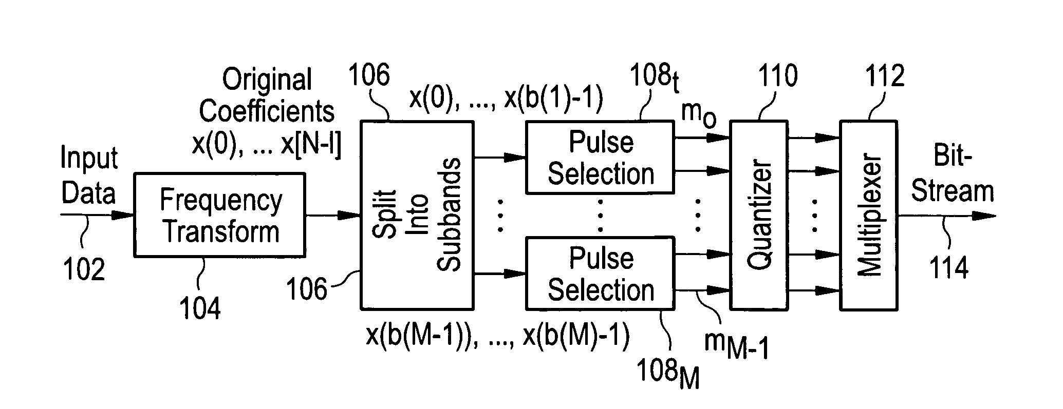
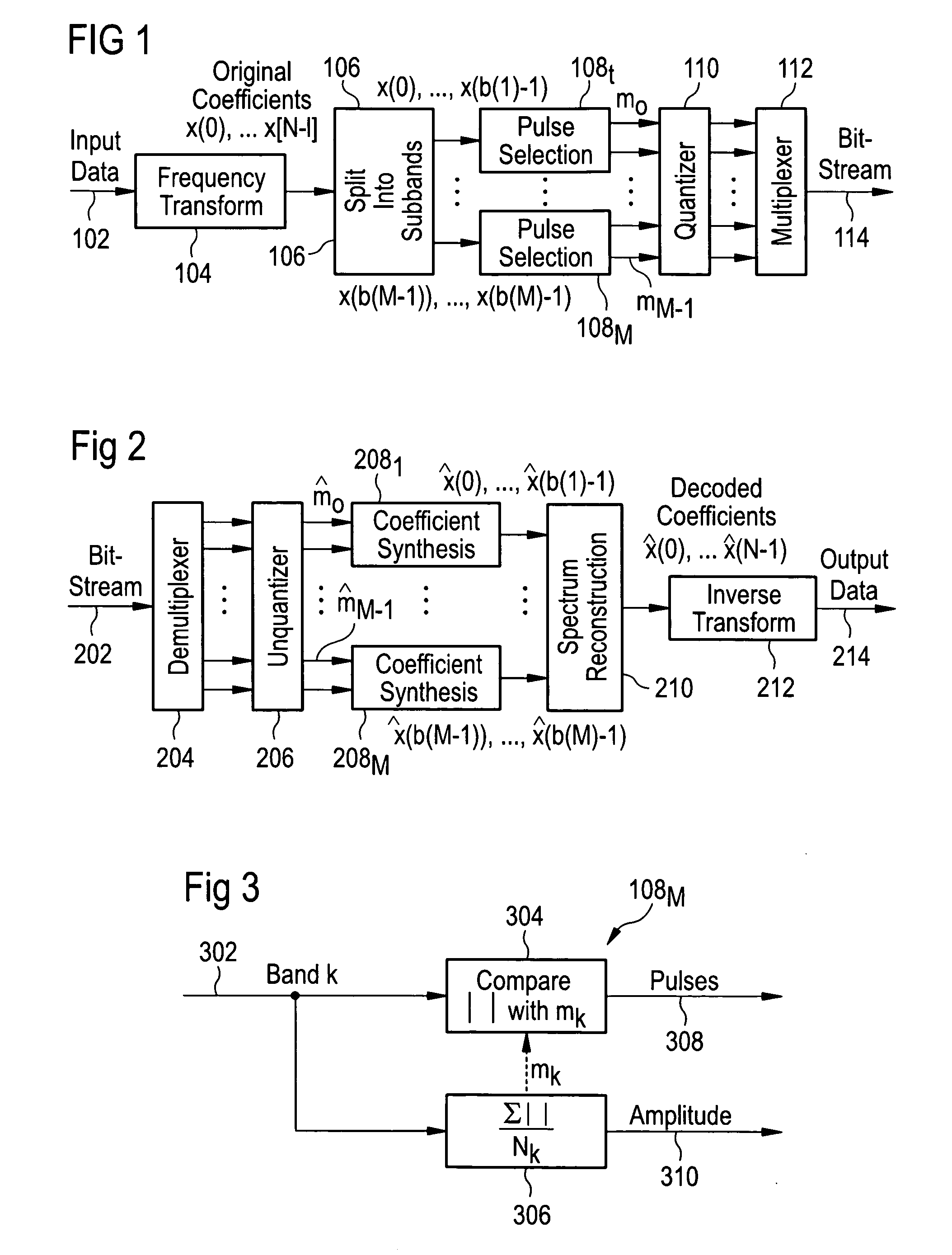
[0068]FIG. 3 shows in more detail the pulse selection block 108M of the encoder of FIG. 2. The pulse selection block 108M comprises an input 302, which is fed both to a pulse determination block 304 and an amplitude value determination block 306, and a first output 308 which outputs pulses determined by the pulse determination block 304 and a second output 310 which outputs an amplitude value determined by the amplitude value determination block 306 and an output 310.

[0069]In operation, the pulse selection block 108M receives a particular band k of a set of coefficients as described above and provides the coefficients to the pulse determination block 304 and the amplitude value determination block 306. By way of example, in one implementation there are fourteen bands, due to a bandwidth limitation of 50-7000 Hz, and ten coefficients per band. The amplitude value determination block 306 calculates an amplitude value mk according to the following equation:

mk=∑j=0Nk-1x(b(k)+j)Nk(1)

[007...

second embodiment

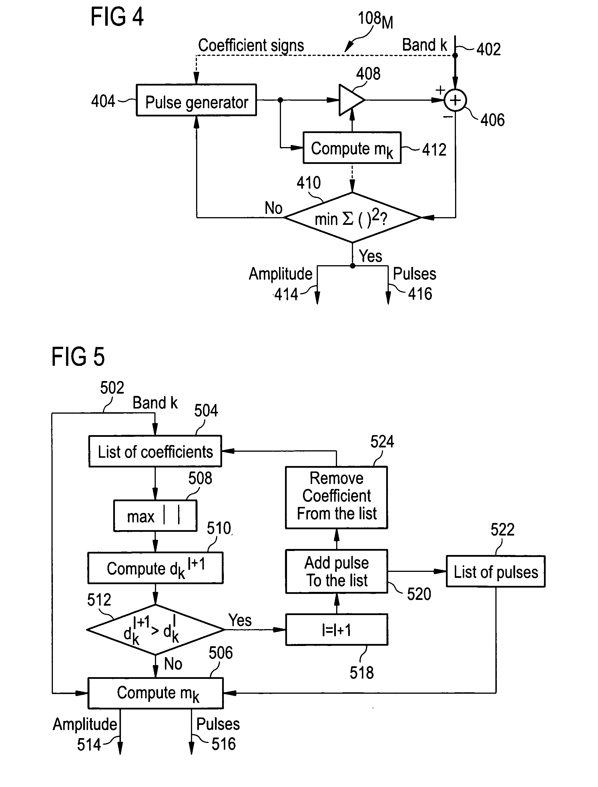
[0074]FIG. 4 shows in more detail the pulse selection block 108M of the encoder of FIG. 2. The pulse selection block 108M comprises an input 402, which is fed both to a pulse generator 404 and a comparator 406, a multiplication block 408, an optimization block 410, an amplitude value calculation block 412, a first output 414, and a second output 416.

[0075]Before operation of the pulse selection block 108M of FIG. 4 is described, the background to its operation in mathematical terms will be set out. The amplitude value mk, the position and signs of the pulses are given by the minimization of the following optimization criterion:

ek=∑j=0Nk-1(x(b(k)+j)-mkc(b(k)+j))2(3)

[0076]A condition for having a minimum is:

∂ek∂mk=0

[0077]In order to determine the minimum, it is necessary for the amplitude value mk to be known. This can be expressed as:

mk=∑j=0Nk-1x(b(k)+j)c(b(k)+j)∑j=0Nk-1c(b(k)+j)2(4)

that is, the absolute values of the selected coefficients added together divided by the number of puls...

third embodiment

[0090]FIG. 5 shows in more detail the pulse selection block 108M of the encoder of FIG. 2. This pulse selection block 108M operates iteratively in order to carry out a coefficient-by-coefficient examination and extract particular pulses for encoding. The pulse selection block 108M comprises an input 502, which is fed both to a coefficient memory 504 and to an amplitude value calculation block 506. The coefficient memory 504 is coupled in sequence to various other blocks: a maximum coefficient selection block 508, a dk computation block 510, a comparison block 512, and (via a “no” branch), the amplitude value calculation block 506. The amplitude value calculation block 506 has two outputs—a first output 514 for an amplitude value and a second output 516 for pulses. In addition to the blocks already described, a branch leading off a “yes” branch of the comparison block 512, is coupled in turn to a counter 518, a pulse collection block 520, and a pulse memory 522 (which are concerned w...


PUM


Abstract

A method of encoding a speech signal for transmission in a communications network involves transforming the signal into a sequence of frames, each frame including a plurality of coefficients; dividing the frame into a set of sub-bands each containing a sub-set of the plurality of coefficients; applying an optimization function to calculate respective test values corresponding to respective candidate sets of pulses representing a coded form of at least some of the coefficients; and selecting a set of pulses having a test value which meets a selectability criterion. If the optimisation function is an error function, the selectability criterion is minimization of the function. If the optimization function is an iterative function, the selectability criterion is selecting an iteration in which a certain condition is reached.

Description

CROSS REFERENCE TO RELATED APPLICATIONS[0001]This application is based on and hereby claims priority to European Application No. EP07012614 filed on Jun. 27, 2007, the contents of which are hereby incorporated by reference.BACKGROUND OF THE INVENTION[0002]This invention relates to an audio coding method and an encoder and decoder for carrying out the same. A mobile terminal or a network element may incorporate an audio encoder and / or decoder for coding and / or decoding an audio signal. The method is particularly applicable to speech coding.[0003]The goal of audio encoding is to reduce the amount of data which is to be transmitted over a link or a channel or which is to be stored (for example on a memory card or in an MP3 player). If the data is being transmitted it may travel over a wireless connection (for example a channel in a mobile telephony system, such as the GSM system) or on a path through several routers in the Internet.[0004]Audio encoding typically involves a plurality of...

Claims


Application Information

Patent Timeline
Patent Type & Authority Applications(United States)
IPC IPC(8): G10L19/00G10L21/00G10L19/02G10L19/032
CPCG10L19/032G10L19/0204
Inventor TADDEI, HERVEDE MEULENEIRE, MICKAEL
Owner NOKIA SOLUTIONS & NETWORKS OY
Features
  • R&D
  • Intellectual Property
  • Life Sciences
  • Materials
  • Tech Scout
  • Unparalleled Data Quality
  • Higher Quality Content
  • 60% Fewer Hallucinations
Learn More