Implantation of cartilage

Inactive Publication Date: 2009-01-22
LIFENET HEALTH
View PDF62 Cites 65 Cited by
  • Summary
  • Abstract
  • Description
  • Claims
  • Application Information

AI Technical Summary

Benefits of technology

[0018]Cartilage grafts may be transplanted containing a viable cell population or as a previously preserved tissue that contains a non-viable cell population (or partially viable cell population) and as a matrix structure that is changed only by the preservation and/or incubation process. The present invention relates to removal of the cell population and modification of the matrix structure such that the matrix will not only recellularize post-implantation, but remain cellular, remodeling into a tissue that maintains structural and functional compatibility. Also considered is the means by which the cartilage graft may be made acellular such that the m

Problems solved by technology

Despite some positive results, issues with tissue rejection, disease transmission and a lack of long-term data have limited the use of this approach.
The damage on the annulus can cause pain and possible disc herniation that can compress nerves or the spinal cord resulting in arm or leg pain and dysfunction.
However, the most common cartilage injury is articular cartilage injury often as a result of sports related trauma.
Due to its avascular nature, articular cartilage has very limi

Method used


Image

  • Implantation of cartilage
  • Implantation of cartilage
  • Implantation of cartilage

Examples


Example

Example 1

Osteochondral Plug, Straight, Step, or Dumbbell Shape

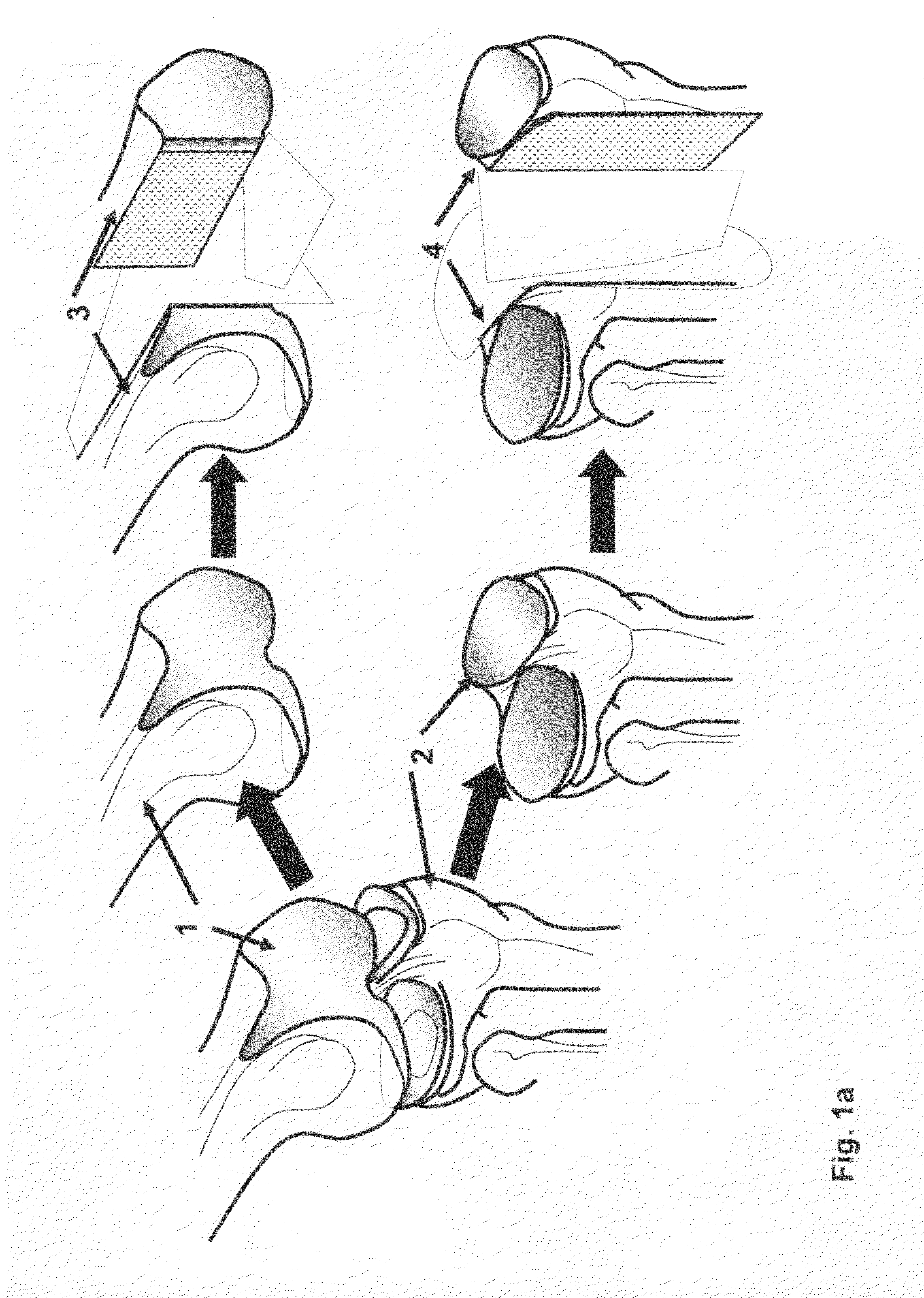
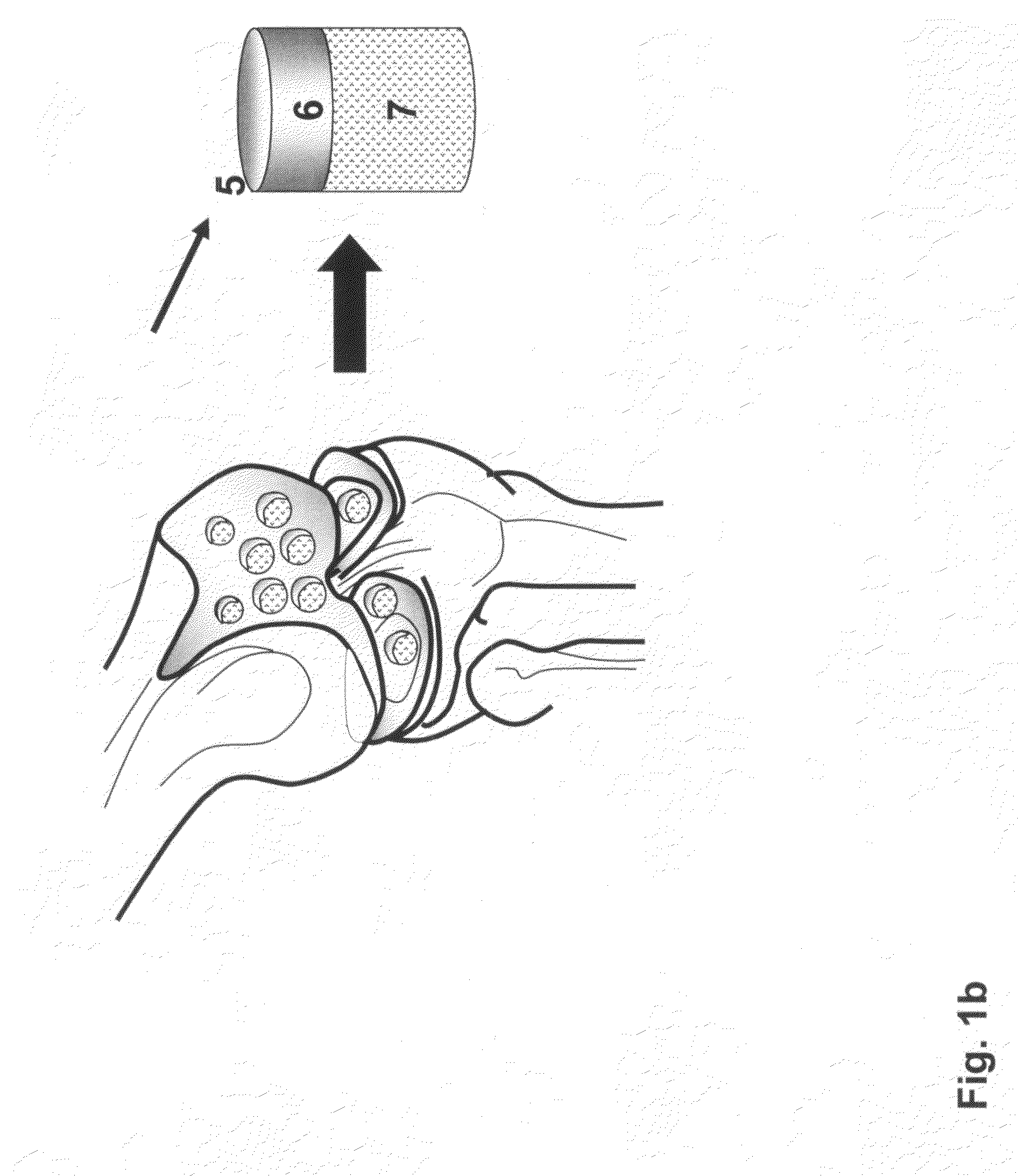
[0133]The distal end of a human femur was procured from a suitable donor, transported on wet ice to the processing facility. A picture was taken and was superimposed on a customer made grid / coordinate system to create a map of the human femoral condyle. The femoral condyle end was “cored” with a coring device or drilled with a hollow cylindrical drill bit to produce multiple cylindrical osteochondral plugs with diameter range from 5-20 mm and the length of the bone portion from 5-20 mm. The coordinate of each individual cylindrical plug was recorded according to the map. The cylindrical plugs were rinsed with isotonic saline. Then one of the cylindrical plugs was inserted into a holder, such as illustrated in FIG. 7, with the cartilage cap positioned face down and supported by the custom made bolt (60) as illustrated in FIG. 7(d, e and f). The length of the bone portion of the osteochondral plug protruding above the top o...

Example

Example 2

Osteochondral Plug with Gaps, Hollow Cylinder, or Multiple Small Cylindrical Channels

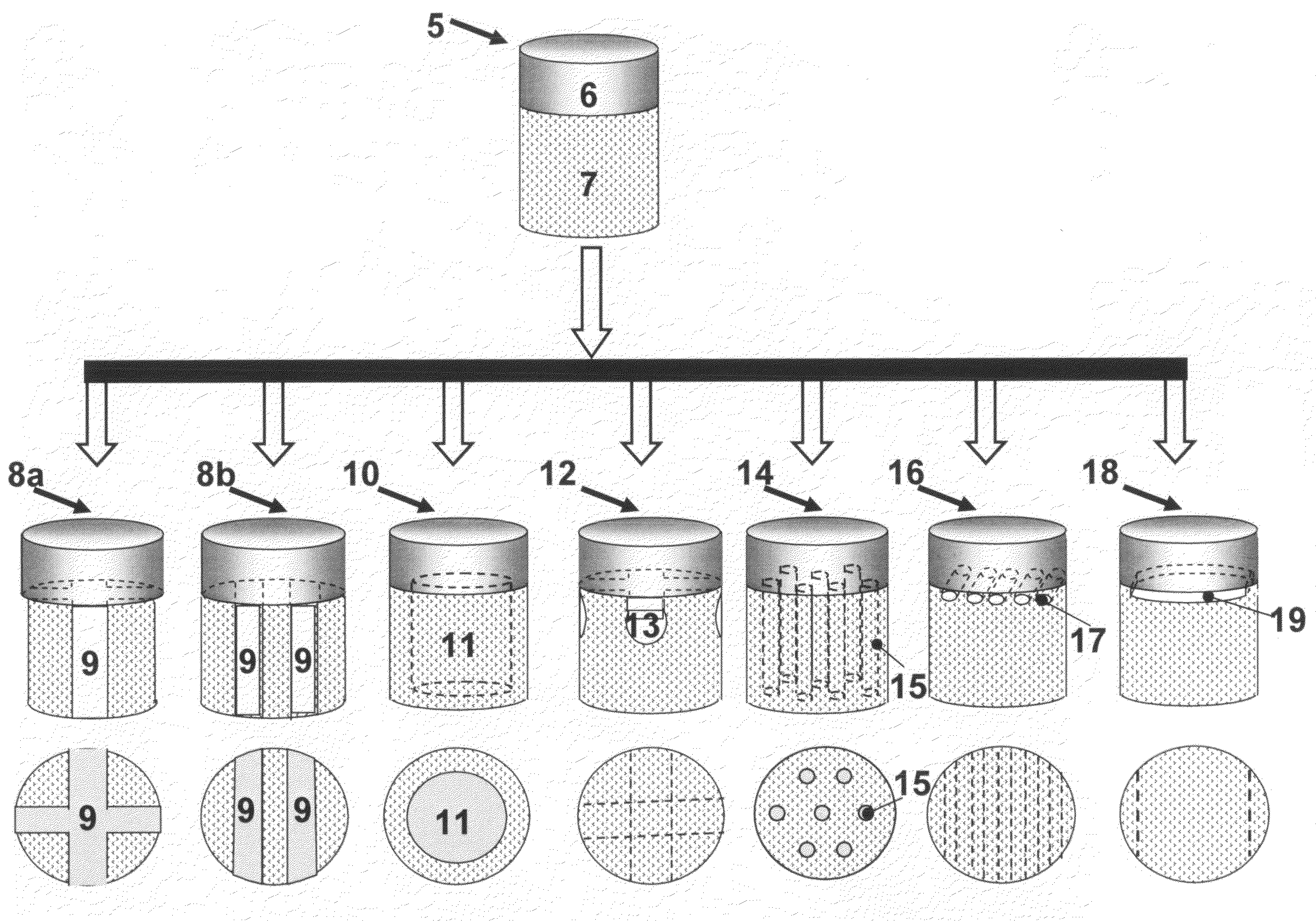
[0135]The osteochondral plugs, crafted to be straight, step cylindrical, or dumbbell shape as illustrated in Example 1 can be further crafted to have channels, gaps, or slots, such as osteochondral plugs (8a, 8b, 10, or 14; 22a, 22b, 23, or 25; 30a, 30b, 31, or 33) illustrated in FIG. 2-FIG. 4. Before being inserted into a holder (63 in FIG. 7), the length of the bone portion of the osteochondral plug was measured. Then, an osteochondral plug, e.g. a dumbbell shape cylindrical plug with 14 mm maximum diameter and 10 mm minimum diameter, was inserted into a holder with the cartilage cap positioned to face down and supported by the custom made bolt (60), as illustrated in FIG. 7(f).

[0136]The length of the bone portion of the osteochondral plug protruding above the top of the holder was adjusted by the custom made bolt (60). Then set screws (57), preferably to be oriented 90 degrees apart, wer...

Example

Example 3

Osteochondral Plug with Channels at the Cartilage / Bone Interface

[0140]The osteochondral plugs, crafted to be straight, step cylindrical, or dumbbell shape as illustrated in Example 1 can be further crafted to have channels at the cartilage cap and bone portion interface, such as osteochondral plugs (12, 24, or 32) illustrated in FIG. 2-FIG. 4. Before being inserted into a holder, the length of the bone portion of the osteochondral plug was measured. Then, the osteochondral plug, e.g. a step cylindrical plug with 10 mm diameter at the bone portion, was inserted into a holder (61), with the cartilage cap positioned to face up and the bottom of the bone portion was supported by the custom made bolt (60) as illustrated in FIG. 8(e). The length of the osteochondral plug protruding above the top of the holder was adjusted by the custom made bolt. Then four set screws (57), preferably oriented 90 degrees apart, were engaged to further secure the osteochondral plug within the holde...


PUM


Abstract

The invention is directed towards a process for implanting a cartilage graft into a cartilage defect and sealing the implanted cartilage graft with recipient tissue by creating a first bore down to the bone portion of the cartilage defect, creating a second shaped bore that is concentric to and on top of the first bore to match the shape and size of the cartilage graft, treating the first bore and the second shaped bore at the defect site with a bonding agent, treating the circumferential area of the cartilage graft with a bonding agent, inserting the cartilage graft into the defect site and wherein the superficial surface of the cartilage graft is at the same height as the surrounding cartilage surface. The first and second bonding agents may be activated by applying a stimulation agent to induce sealing, integration, and restoration of the hydrodynamic environments of the recipient tissue. The invention is also directed towards a process for repairing a cartilage defect and implanting a cartilage graft into a human or animal by crafting a cartilage matrix into individual grafts, cleaning and disinfecting the cartilage graft, applying a pretreatment solution to the cartilage graft, removing cellular debris using an extracting solution to produce a devitalized cartilage graft, implanting the cartilage graft into the cartilage defect with or without an insertion device, and sealing the implanted cartilage graft with recipient tissue. The devitalized cartilage graft is optionally recellularized in vitro, in vivo, or in situ with viable cells to render the tissue vital before or after the implantation. The devitalized cartilage graft is also optionally stored between the removing cellular debris and the recellularizing steps. The invention is further directed toward a repaired cartilage defect.

Description

FIELD OF THE INVENTION[0001]The invention is directed towards a process for implanting a cartilage graft into a cartilage defect and sealing the implanted cartilage graft with recipient tissue. This application claims priority to 3 cofiled and copending applications, which are incorporated by reference herein in their entireties.BACKGROUND OF THE INVENTION[0002]Cartilage is a highly hydrated connective tissue with chondrocytes embedded in a dense extracellular matrix made of, for example, collagen, proteoglycan and water. Although the biochemical composition of cartilage differs according to types, there are mainly three types of cartilage present in a mammal, which include: articular or hyaline cartilage, fibrocartilage, and elastic cartilage. Hyaline cartilage is predominantly found on the articulating surfaces of articulating joints and contains type II collagen and proteoglycans. It is found also in epiphyseal plates, costal cartilage, tracheal cartilage, bronchial cartilage, an...

Claims


Application Information

Patent Timeline
IPC IPC(8): A61F2/02A61F2/28
CPCA61B17/1604A61L2430/06A61B17/1675A61F2/28A61F2/30749A61F2/30756A61F2/3094A61F2/38A61F2/3859A61F2/4644A61F2002/2817A61F2002/2839A61F2002/30004A61F2002/30224A61F2002/30235A61F2002/30751A61F2002/30759A61F2002/30762A61F2002/30764A61F2002/4646A61F2002/4648A61F2002/4649A61F2230/0069A61F2250/0014A61L27/3612A61L27/3654A61L27/3683A61L27/3804A61B17/1635
Inventor CHEN, SILVIA S.QIN, XIAOFEICHEN, JINGSONGWOLFINBARGER, JR., LLOYD
Owner LIFENET HEALTH
Why Eureka
Try Eureka