Refrigeration System

a refrigeration system and compressor technology, applied in the field of refrigeration systems, can solve the problem that it is highly unlikely that the outside temperature acting on the cooling load changes so abruptly, and achieve the effect of reducing the operating power of the compressor (11), and enhancing the energy saving performance of the refrigeration system

Active Publication Date: 2009-01-29
DAIKIN IND LTD
View PDF16 Cites 17 Cited by
  • Summary
  • Abstract
  • Description
  • Claims
  • Application Information

AI Technical Summary

Benefits of technology

[0045]According to the first aspect of the invention, since the compressor (11) is intermittently driven during the energy saving operation, this reduces the operating power of the compressor (11) and in turn enhances the energy saving performance of the refrigeration system.
[0046]Particularly in this aspect of the invention, the internal cold storage temperature is once lowered to the lower limit by the second action and the compressor (11) is then stopped. Furthermore, the compressor (11) is held stopped until the internal cold storage temperature reaches the upper limit during the third action. Therefore, according to this aspect of the invention, as compared to the case where the compressor is stopped without once lowering the internal cold storage temperature to the lower limit, the time for the internal cold storage temperature to reach the upper limit can be extended and the compressor can be stopped for an accordingly longer period of time. Hence, the operating power of the compressor (11) during the energy saving operation can be further reduced, thereby effectively reducing the energy consumed by the refrigeration system.
[0047]Furthermore, according to this aspect of the invention, since the capacity of the cooling heat exchanger (14) and the on/off operation of the compressor (11) are controlled so that the internal cold storage temperature can change between the upper and lower limits of the desired temperature range, it can be avoided that the internal cold storage temperature deviates from the desired temperature range. Therefore, the interior of the cold storage can be surely cooled also during the energy saving operation, which enhances the reliability of the refrigeration system.
[0048]Particularly in the second aspect of the invention, the cooling capacity of the cooling heat exchanger (14) is regulated by regulating the amount of flow of refrigerant to be sucked into the compressor (11) with the flow regulator valve (35). Therefore, refrigerant on the wet side is accumulated in the entire area of the cooling heat exchanger (14

Problems solved by technology

In addition, it is highly unlikely that the outside temperature acting on the cooling load changes so abruptly.
Even in such cases, however

Method used


Image

  • Refrigeration System
  • Refrigeration System
  • Refrigeration System

Examples


Embodiment Construction

[0071]An embodiment of the present invention will be described below in detail with reference to the drawings.

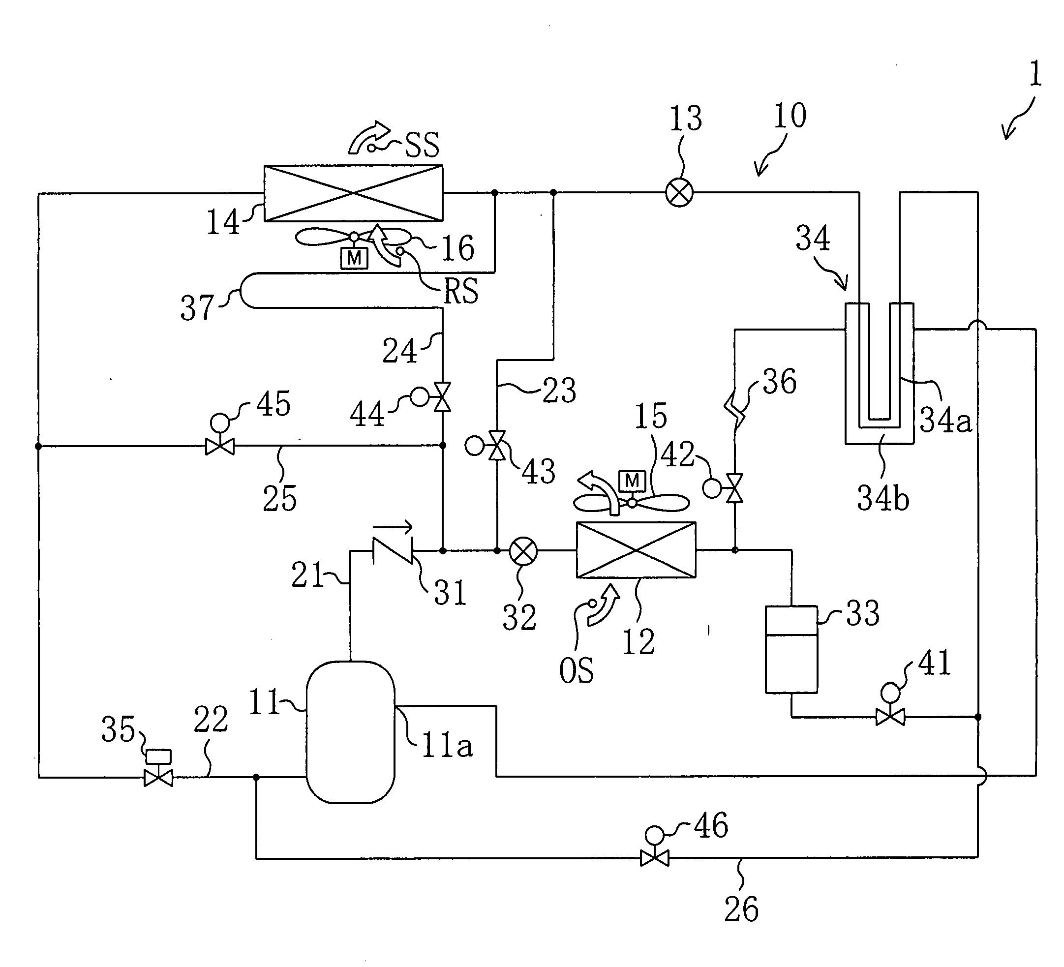
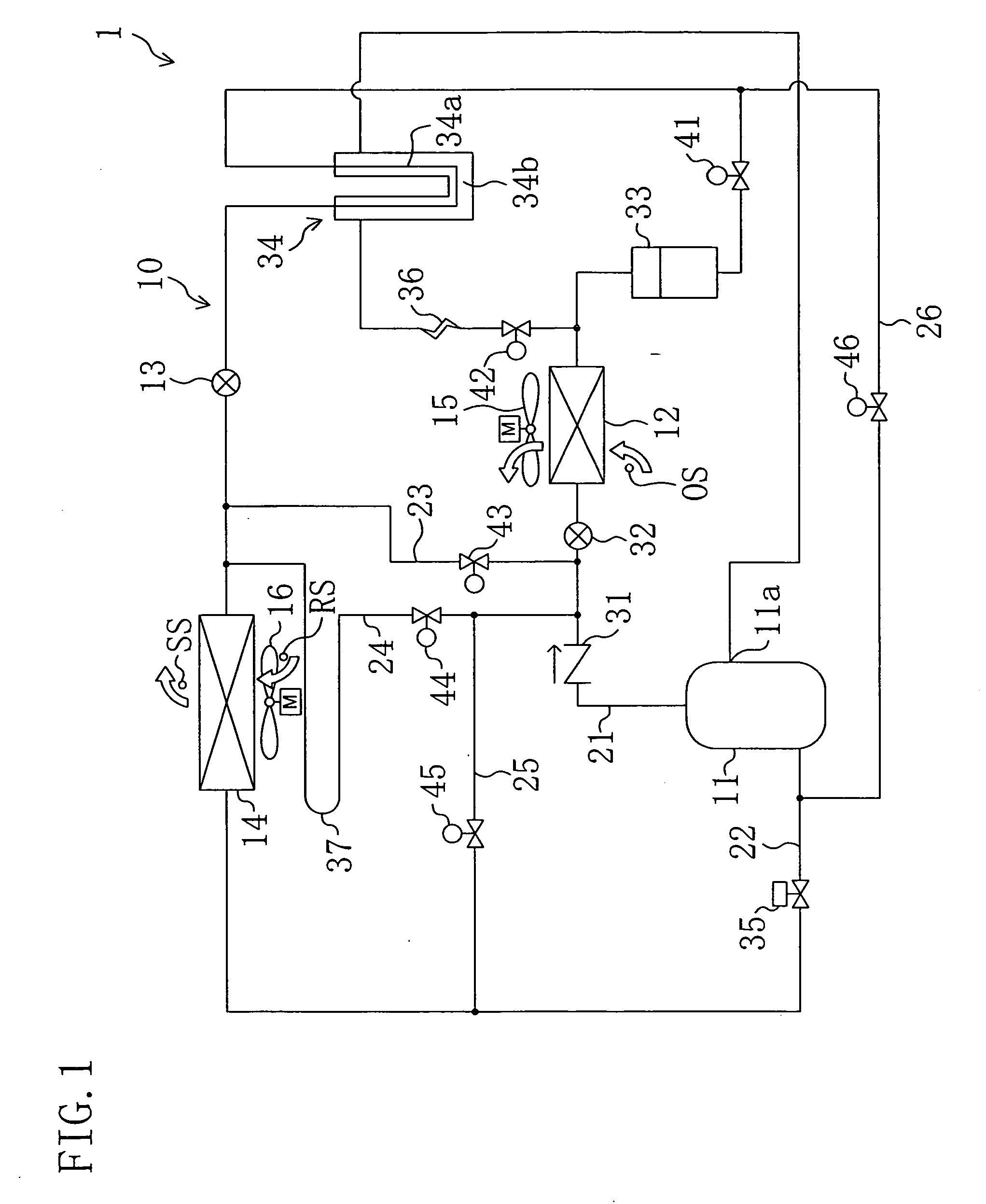
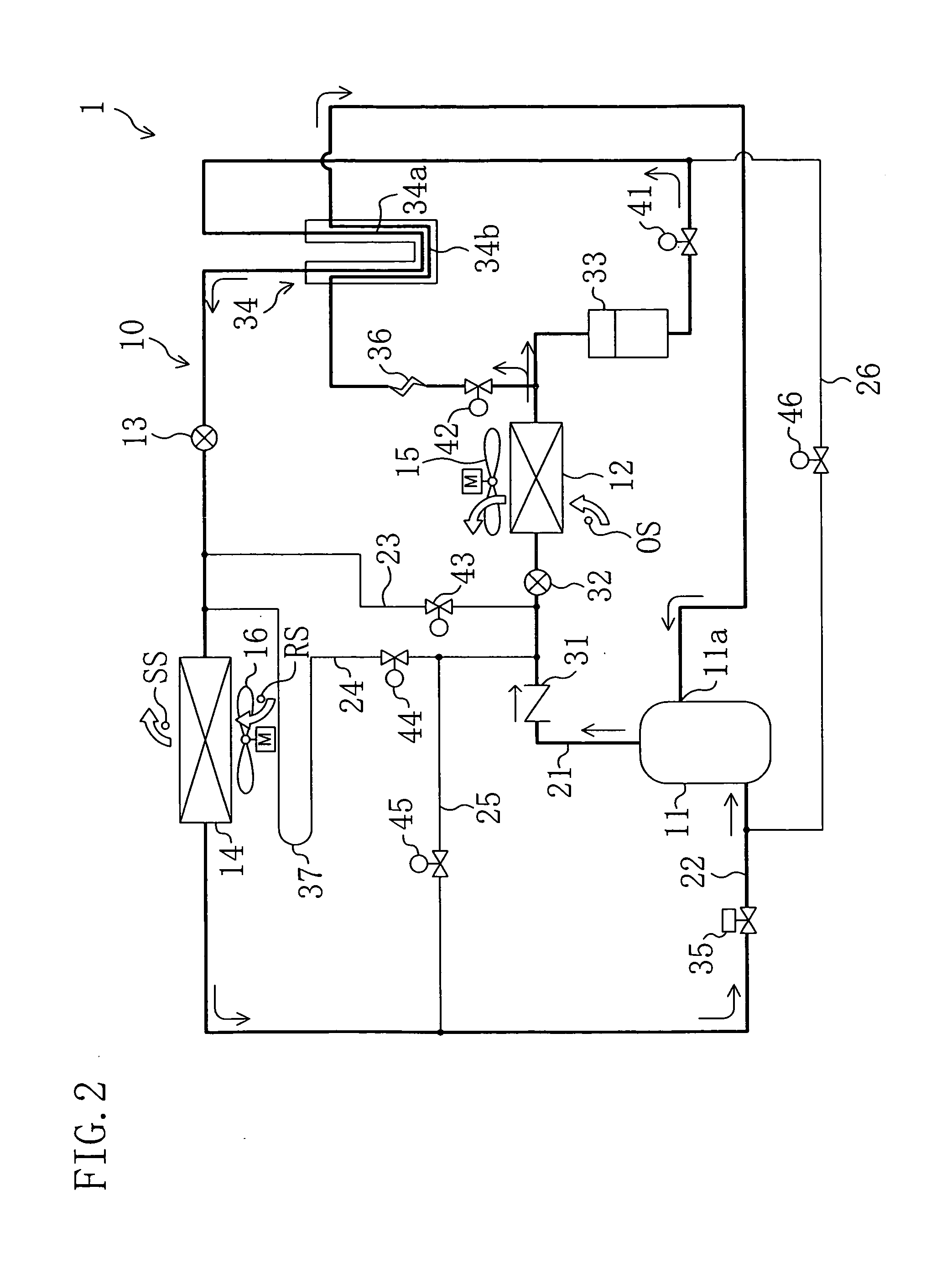
[0072]The refrigeration system (1) of this embodiment is used for cooling the interior of a cold storage in a container for use in sea transport or other transports. The refrigeration system (1) includes a refrigerant circuit (10) operating in a vapor compression refrigeration cycle by circulating refrigerant therethrough.

[0073]The refrigerant circuit (10) includes, as main components, a compressor (11), a condenser (12), an expansion valve (13) and an evaporator (14) all connected therein.

[0074]The compressor (11) is composed of a fixed displacement scroll compressor whose motor has a constant rotational speed. The condenser (12) is placed outside the cold storage and constitutes a so-called air-cooled condenser. Disposed close to the condenser (12) is an external fan (15) for feeding external air to the condenser (12). Furthermore, the condenser (12) provides heat exchange...


PUM


Abstract

When during a first action of a refrigeration system the internal cold storage temperature is held at a desired temperature by an evaporator, the refrigeration system performs a second action of increasing the cooling capacity of the evaporator to decrease the internal cold storage temperature. When during the second action the internal cold storage temperature reaches a minimum temperature Tmin, the refrigeration system stops a compressor and performs a third action. When during the third action the internal cold storage temperature reaches a maximum temperature Tmin, the refrigeration system drives the compressor and performs the first action.

Description

TECHNICAL FIELD[0001]This invention relates to a refrigeration system with a cooling heat exchanger for cooling the interior of a cold storage and particularly relates to a method for energy saving operation of the refrigeration system.BACKGROUND ART[0002]Refrigeration systems are conventionally known for cooling the interior of a cold storage, such as a chiller or a freezer.[0003]For example, Patent Document 1 discloses a refrigeration system for cooling the interior of a cold storage in a container for use in sea transport or other transports. This refrigeration system includes a refrigerant circuit in which a compressor, a condenser, an expansion valve and a cooling heat exchanger (evaporator) are connected. The refrigerant circuit in the refrigeration system operates in a vapor compression refrigeration cycle by circulating refrigerant therethrough. As a result, the refrigerant flowing through the cooling heat exchanger takes heat from air in the cold storage to evaporate and th...

Claims


Application Information

Patent Timeline
IPC IPC(8): F25B1/00F25D17/06F25B29/00
CPCF25B1/10F25B41/043F25B49/022Y02B30/743F25B2600/0251F25B2600/112F25D29/003F25B2400/13F25B41/22Y02B30/70
Inventor TANAKA, SHIGETOKAWAKATSU, NORIYASU
Owner DAIKIN IND LTD
Why Eureka
Try Eureka