Dispersion compensator, solid-state laser apparatus using the same, and dispersion compensation method

a laser and compensator technology, applied in the direction of instruments, mirrors, laser details, etc., can solve the problems of increased laser equipment and instability, low loss, low cost, and high stability, and achieve the effect of reducing the size of the variable dispersion compensator, increasing the range, and reducing the negative dispersion varian

Inactive Publication Date: 2009-01-29
FUJIFILM CORP
View PDF33 Cites 12 Cited by
  • Summary
  • Abstract
  • Description
  • Claims
  • Application Information

AI Technical Summary

Benefits of technology

[0088]More specifically, as illustrated in FIG. 7, if the distance between the mirrors is d and the incident angle is θ, a projection Y of a beam incident on the negative dispersion mirror 2 from the negative dispersion mirror 1 on the y axis may be expressed by the formula below, provided that Φ is a rectangular coordinate system parallel to the optical axis.
[0089]Accordingly, it is only necessary to move the negative dispersion mirror 2, for example, by mounting on an actuator such that a variation in the projection Y with respect to a variation in the incident angle θ is corrected based on the formula above. A movement amount D of the negative dispersion mirror 2 is given by the formula below, though the detailed calculation process is omitted here. Note that θ′ in the formula is the incident angle after rotation.
[0090]Next, a variable dispersion compensator 50 according to a fifth embodiment of the present invention will be described with reference to FIG. 8. In the present embodiment, a mirror having a group velocity dispersion distribution on the surface thereof is used as the negative dispersion mirror 2. That is, as the negative dispersion mirror 2 is rotated, the incident position of the input laser beam Bin on the mirror is changed and the amount of negative dispersion of the negative dispersion mirror 2 varies along the changing direction of the incident position.
[0091]In this case, the pair of negative dispersion mirrors 1 and 2 is rotated, and the dependence of negative dispersion thereof on the rotation angle is basically utilized, as in the first embodiment. When the disposed state of the negative dispersion mirror 2 is c...

Problems solved by technology

So far, however, an optical component having a size allowing insertion in a resonator and variability in the amount of dispersion compensation with low loss, low cost, and high stability has not been proposed yet.
An increased resonator length is likely to induce an increased size of laser equipment and instability due to mechanical variations.
In the mean time, employment of the diffraction grating pair causes significant attenuation in laser output due to optical power loss of inserted diffraction grating pair since the diffraction efficiency thereof is around 80% at a maximum.
But, variability of dispersion compensation is compromised, since the compensation amount is limited to the predetermined value coated on th...

Method used


Image

  • Dispersion compensator, solid-state laser apparatus using the same, and dispersion compensation method
  • Dispersion compensator, solid-state laser apparatus using the same, and dispersion compensation method
  • Dispersion compensator, solid-state laser apparatus using the same, and dispersion compensation method

Examples


first embodiment

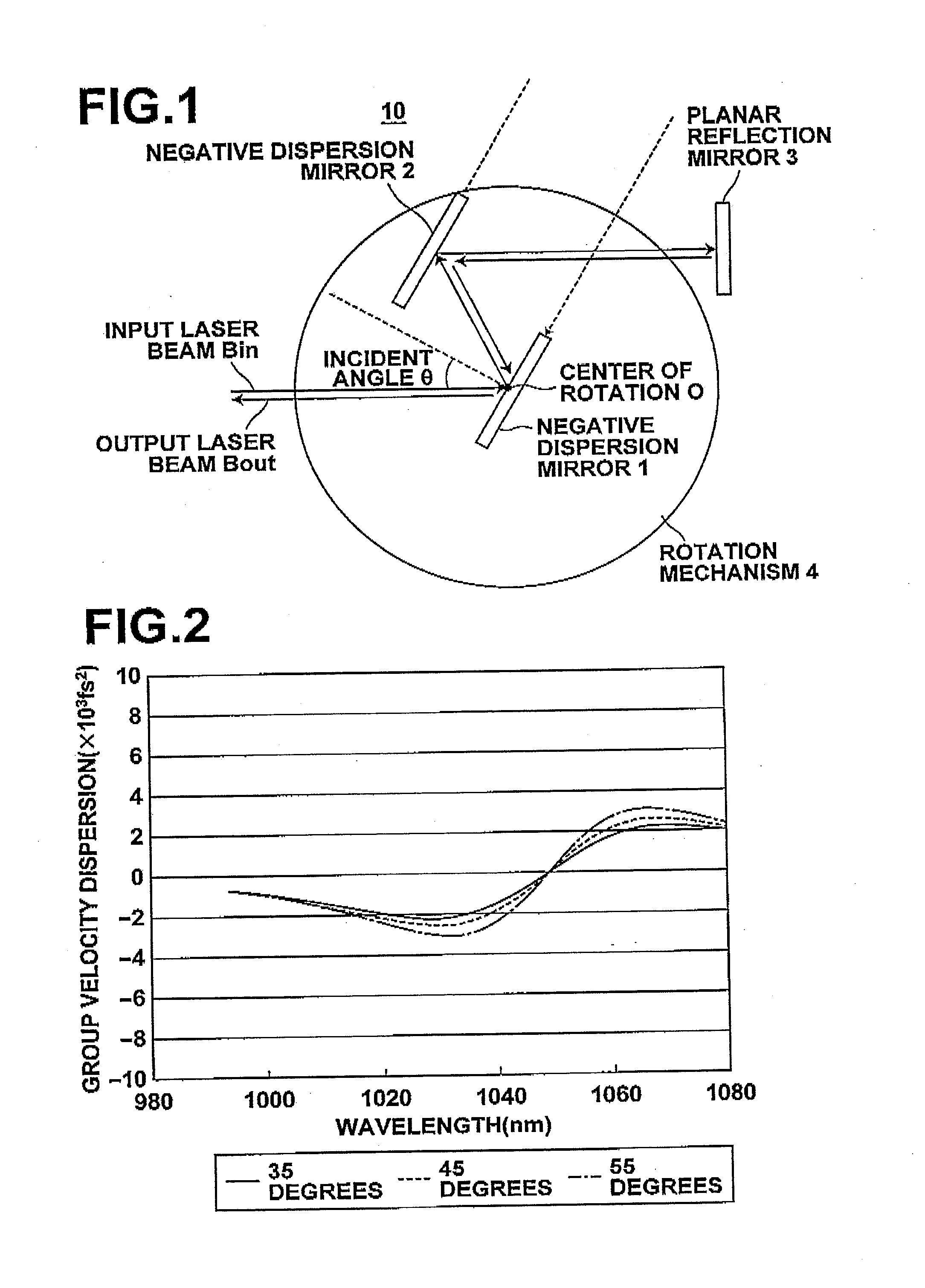
[0067]FIG. 1 illustrates a variable dispersion compensator 10 according to a The variable dispersion compensator 10 includes so-called GTI mirrors using etalon interference as negative dispersion mirrors (dispersion compensation mirrors). However, any type of mirrors other than the GTI mirrors may also be used as long as they provide negative dispersion which is dependent on incident angle.

[0068]A negative dispersion mirror 1 (first mirror) and a negative dispersion mirror 2 (second mirror) of the type described above are disposed parallel to each other on a rotation mechanism 4 rotatable around a center of rotation O. A planar reflection mirror 3 is disposed outside of the rotation mechanism 4 as a third mirror such that light from the negative dispersion mirror 2 is incident thereon at normal incidence. The optical path of an input laser beam Bin is set so as to incident on the negative dispersion mirror 1. In the present embodiment, the center of rotation O of the rotation mecha...

second embodiment

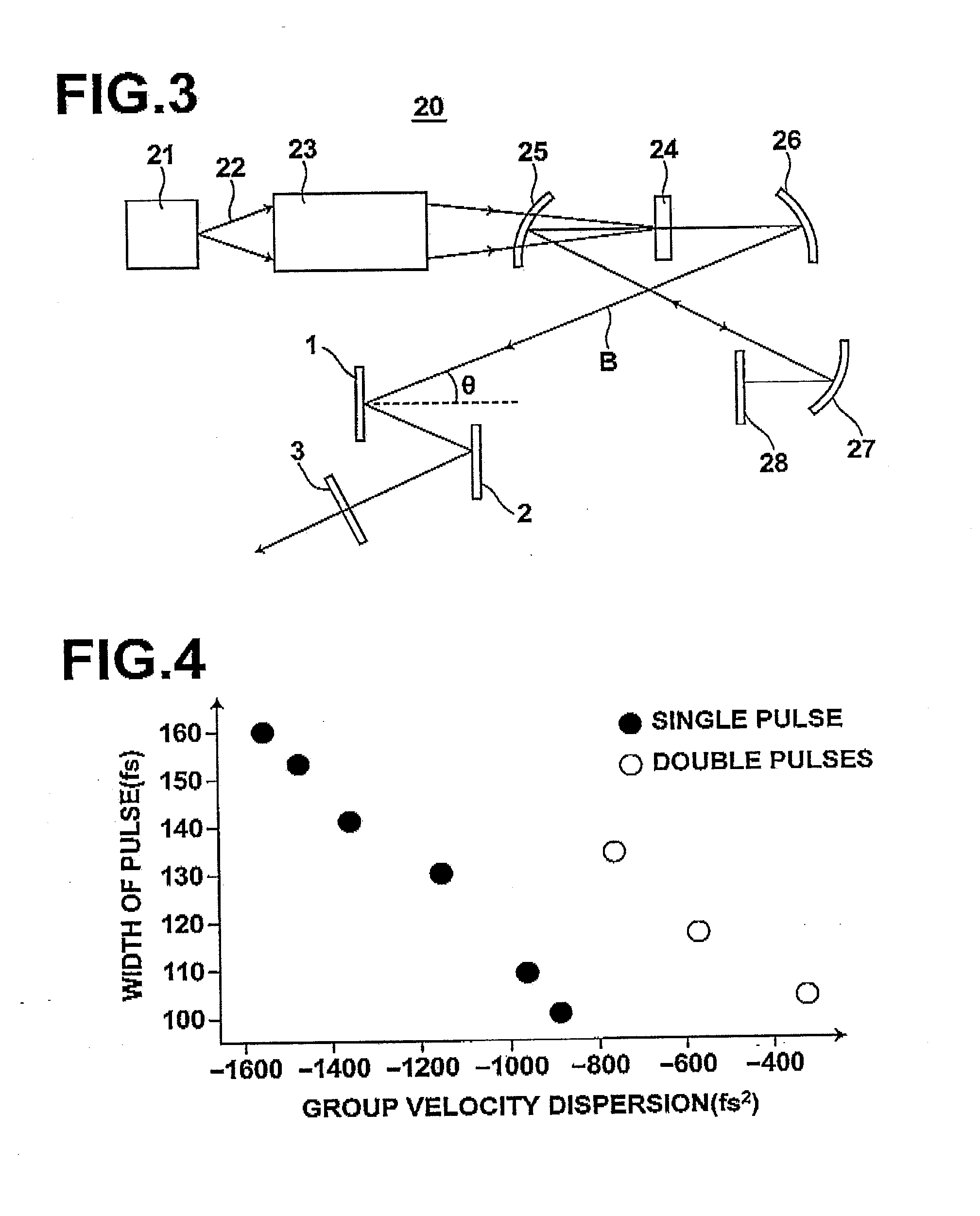
[0078]Next, a solid-state laser apparatus 20 will be described with reference to FIG. 3. The solid-state laser apparatus 20 is formed with the variable dispersion compensator 10 shown in FIG. 1 inserted in a mode locking laser oscillator, and includes: an excitation laser 21; an excitation optical system 23 that collimates and focuses an excitation laser beam 22 emitted from the excitation laser 21; a laser crystal 24 disposed at a focus position of the excitation laser beam 22 focused by the excitation optical system 23; concave mirrors 25, 26 disposed opposite to each other with the excitation optical system 23 between them; a concave mirror 27 disposed at a position where a solid-state laser beam B reflected by the concave mirror 25 is incident; and a semiconductor saturable absorbing mirror (SESAM) 28 disposed such that the solid-state laser beam B is incident thereon at normal incidence.

[0079]As for the excitation laser 21, for example, a semiconductor laser that emits the las...

third embodiment

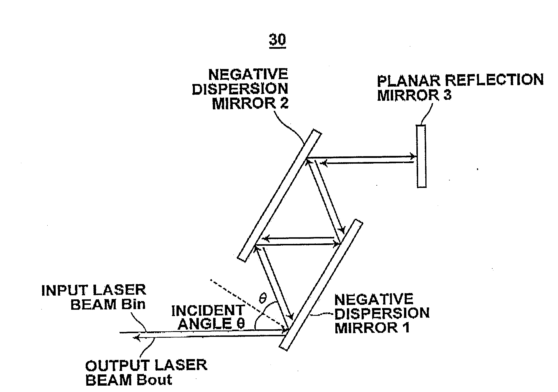
[0083]The optimum value of the dispersion compensation is a function of laser medium used, excitation density, output coupling ratio of output mirror, internal loss, wavelength range and the like, and varies largely. Where the absolute value of dispersion amount is insufficient, it is desirable to cause multiple reflections to occur between the negative dispersion mirrors 1 and 2 as in a variable dispersion compensator 30 illustrated in FIG. 5. That is, the amount of dispersion in reciprocation may be increased by increasing the number of reflections in this way.

[0084]Further, the variable amount provided by the negative dispersion mirrors 1 and 2 is limited. Therefore, it is conceivable to give a fixed amount of dispersion to the planar reflection mirror 3 so that an optimum value of dispersion falls within a dispersion amount range covered by the dispersion compensator.

[0085]A variable dispersion compensator 40 according to a fourth embodiment illustrated in FIG. 6 may keep the i...


PUM


Abstract

A dispersion compensator which is compact, low loss, low cost, and highly stable, and yet capable of varying the dispersion compensation amount without changing the output position of an output beam. The dispersion compensator includes: a first and a second planar mirrors disposed parallel to each other, wherein at least either one of the mirrors has group velocity dispersion whose value varies according to the incident angle of light incident on the mirror; a mirror holding means rotatably holding the first and second mirrors in a direction in which the incident angle of light incident on the first mirror is changed while maintaining the parallel state of the mirrors; and a third mirror disposed so as not to be rotated with the first and second mirrors and reflects light reflected sequentially by the first mirror and the second mirror.

Description

BACKGROUND OF THE INVENTION[0001]1. Field of the Invention[0002]The present invention relates to a dispersion compensator that gives group velocity dispersion in a laser resonator and a dispersion compensation method. The invention also relates to a solid-state laser apparatus having the dispersion compensator described above.[0003]2. Description of the Related Art[0004]Dispersion compensators in which a solid-state laser medium doped with a rare earth ion (or a transition metal ion) is excited by excitation light emitted from a semiconductor laser (LD) and the like have been actively developed. Among them, so-called short pulse lasers having a pulse width in the range from picoseconds to femtoseconds have been proposed in many application areas including medicine, biology, machine industry, and measurement fields, and some of them are put into practical use after verification. These lasers generate ultrashort pulses through so-called mode locking. To put it briefly, the mode lockin...

Claims


Application Information

Patent Timeline
IPC IPC(8): H01S3/08G02B5/08
CPCH01S3/08036H01S3/1112H01S3/105H01S3/0811
Inventor KASAMATSU, TADASHI
Owner FUJIFILM CORP
Why Eureka
Try Eureka