Suspension board with circuit

a suspension board and circuit technology, applied in special recording techniques, magnetic recording, and recording information storage, etc., can solve the problems of troublesome production process, layout restrictions, and difficulty in disposing other components in space, so as to ensure design flexibility, improve production efficiency, and increase spatial margin

Inactive Publication Date: 2009-02-05
NITTO DENKO CORP
View PDF6 Cites 10 Cited by
  • Summary
  • Abstract
  • Description
  • Claims
  • Application Information

AI Technical Summary

Benefits of technology

[0008]Moreover, when the optical waveguide has a curved portion under such layout restrictions, an optical signal travels straight without curving along the curved portion, and easily leaks. This leads to a problem that the optical signal is difficult to be transmitted in an amount of light necessary for the optically assisted method.
[0009]It is therefore an object of the present invention to provide a suspension board with circuit which can adopt an optically assisted method, but can also ensure design flexibility, improve production efficiency, reduce production cost, and further prevent the leakage of an optical signal.
[0013]In the suspension board with circuit according to the present invention, the optical waveguide used in an optically assisted method can be formed with a higher spatial margin than that in a head slider. As a result, it is possible to ensure design flexibility, improve production efficiency, and reduce production cost.
[0014]In addition, since the surface of the curved portion is coated with the metal thin film, an optical signal is reflected by the metal thin film in the curved portion and transmitted along the curved portion, while being confined in the core layer. As a result, it is possible to prevent the leakage of the optical signal at the curved portion and transmit the optical signal in an amount of light necessary for the optically assisted method.

Problems solved by technology

However, because the head slider is formed relatively small to respond to a request for size reduction, and the magnetic head is also provided, it is difficult to dispose other components in terms of space.
Therefore, when the optical waveguide and the light source, each used in the optically assisted method, are to be provided in the head slider together with the magnetic head, a problem arises such as layout restrictions, troublesome production process, and increase in production cost.
Moreover, when the optical waveguide has a curved portion under such layout restrictions, an optical signal travels straight without curving along the curved portion, and easily leaks.
This leads to a problem that the optical signal is difficult to be transmitted in an amount of light necessary for the optically assisted method.

Method used


Image

  • Suspension board with circuit
  • Suspension board with circuit
  • Suspension board with circuit

Examples


example 1

Embodiment in which Metal Thin Film is Formed in Curved Portions

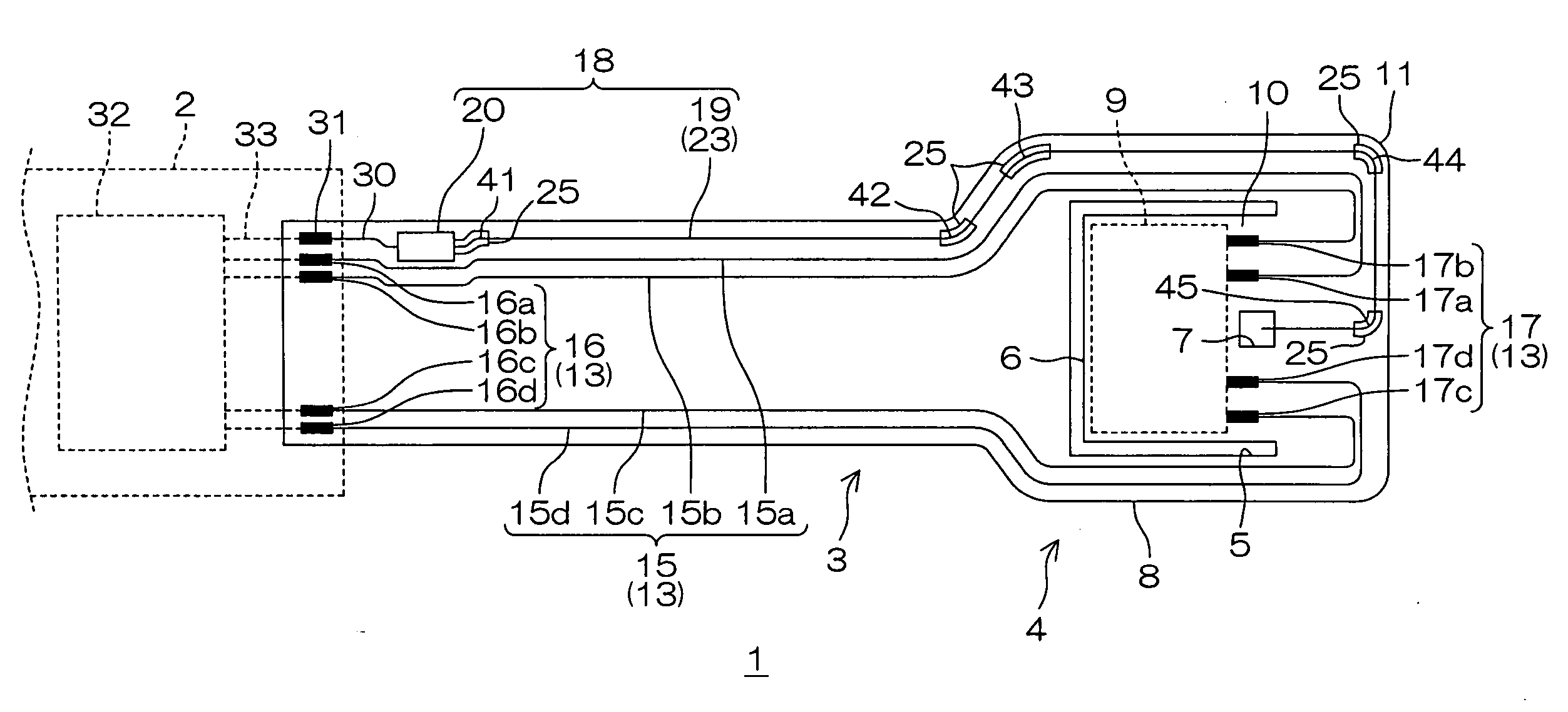
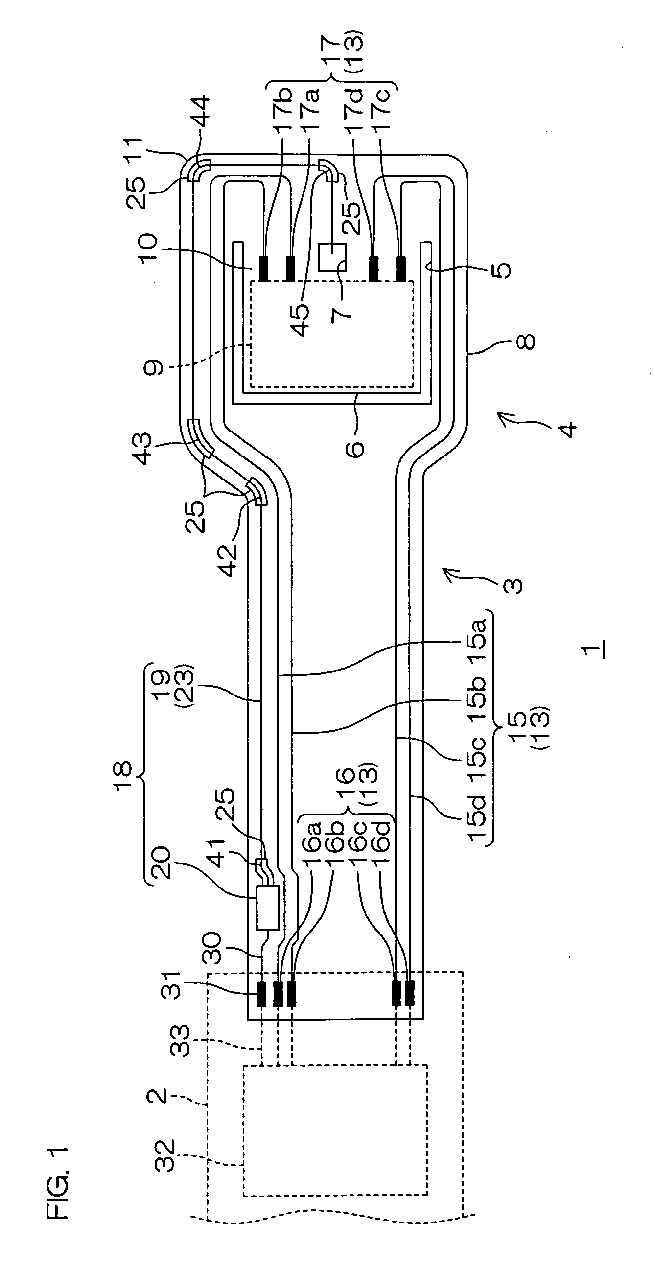
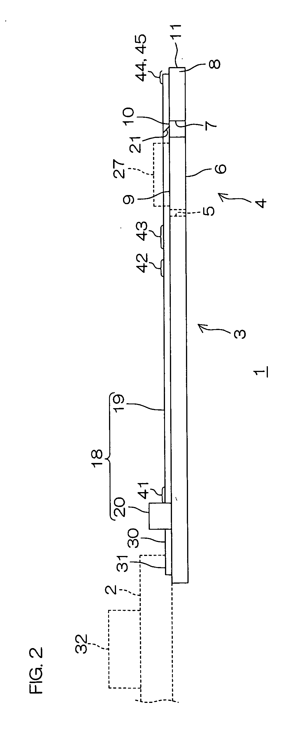
[0178]A metal supporting board made of stainless steel having a thickness of 20 μm was prepared (see FIG. 4(a)).

[0179]Next, an insulating base layer made of a polyimide resin was formed in the foregoing pattern on the metal supporting board (see FIG. 4(b). The refractivity of the insulating base layer at a wavelength of 830 nm was 1.532. The thickness of the insulating base layer was 6 μm.

[0180]Next, a conductive pattern, a supply wire, and a supply terminal portion, each made of copper, were simultaneously formed on the insulating base layer by an additive method (see FIG. 4(c)). The thickness of each was 10 μm.

[0181]Next, a core layer having a first curved portion, a second curved portion, a third curved portion, a fourth curved portion, and a fifth curved portion was formed on the insulating base layer.

[0182]To form the core layer in the foregoing pattern, a varnish was prepared first by mixing 30 parts by weight of ...


PUM


Abstract

A suspension board with circuit includes a metal supporting board, an insulating base layer formed on the metal supporting board, a conductive pattern formed on the insulating base layer, an insulating cover layer formed on the insulating base layer so as to cover the conductive pattern, and an optical waveguide including a core layer having a curved portion and a metal thin film covering a surface of the curved portion.

Description

CROSS REFERENCE TO RELATED APPLICATION[0001]This application claims the benefit of U.S. Provisional Application No. 60 / 935,468, filed Aug. 14, 2007, and claims priority from Japanese Patent Application No. 2007-199997, filed Jul. 31, 2007, the contents of which are herein incorporated by reference in their entirety.BACKGROUND OF THE INVENTION[0002]1. Field of the Invention[0003]The present invention relates to a suspension board with circuit and, more particularly, to a suspension board with circuit mounted on a hard disk drive or the like adopting an optically assisted method.[0004]2. Description of the Related Art[0005]In recent years, as a method of magnetic recording to a hard disk or the like, an optically assisted method (optically assisted magnetic recording method) has been known, which enables high-density information recording with a small recording magnetic field by heating the hard disk with light radiation during recording of information to lower the coersive force ther...

Claims


Application Information

Patent Timeline
Patent Type & Authority Applications(United States)
IPC IPC(8): H01R12/04
CPCG11B5/02G11B2005/0021G11B2005/0005G11B5/4833G11B21/21G11B11/10
Inventor KHAN, SAZZADUR RAHMAN
Owner NITTO DENKO CORP
Why Eureka
Try Eureka